Build LoRa node using Dragino shield v1.1 and Arduino Uno
Information
none
Operating system used
macOS Mojave
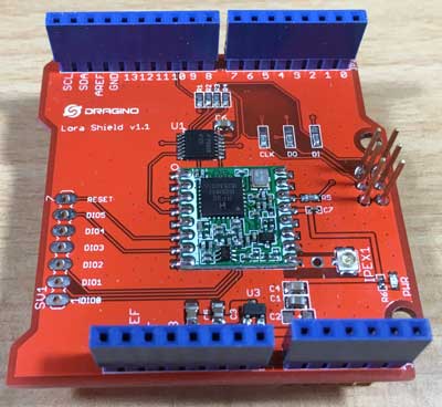
Hardware used
Software prerequisites
none
Procedure
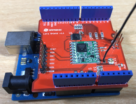
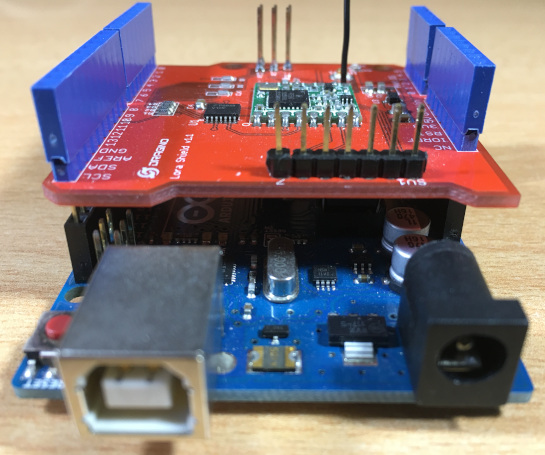
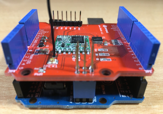
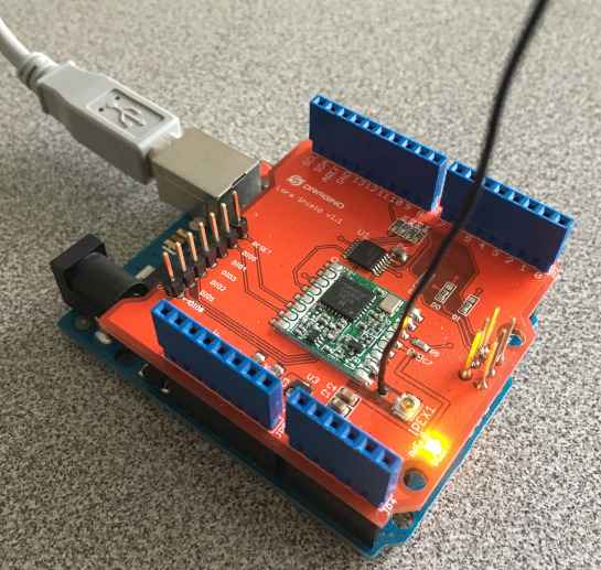
- Mount the Dragino LoRa shield on top of the Arduino Uno.
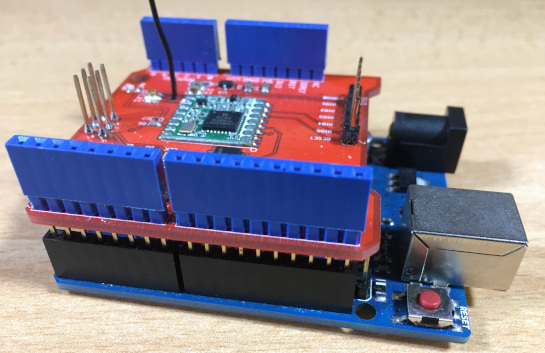
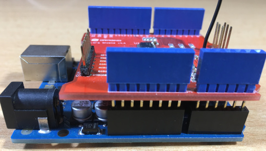
- Attach the USB cable to the Arduino Uno.
- Start Arduino IDE.
I am using Arduino IDE 1.8.10.
This Arduino IDE version uses Arduino AVR Boards version 1.8.1
See:
Arduino menu: Tools | Board: Arduino/Genuino Uno | Boards Manager
Note:
I have used Arduino IDE 1.8.13 (Arduino AVR Boards version 1.8.3) to upload my sketch to my LoRa node.
For unknown reasons the LoRa node does not transmits the data at the specified time.
When I use Arduino IDE 1.8.10 (Arduino AVR Boards version 1.8.1) this problem does not occur.
- Make sure there is no LMIC library is installed.
How to check this:
- Arduino menu: Sketch | Include Library | Manage Libraries...
Type: All
Topic: All
Search field enter: lmic
If there is an LMIC library installed, remove it.
-
It is also possible that you manually installed an LMIC library.
Goto the Arduino library location (OSX: ~/Documents/Arduino/libraries) and check if there is no LMIC library installed.
- Now install the mcci-catena/arduino-lmic (https://github.com/mcci-catena/arduino-lmic)
This can be easily done by:
Arduino menu: Sketch | Include Library | Manage Libraries...
Search field enter: lmic
Select "MCCI LoRaWAN LMIC library"
DO NOT INSTALL:
- IBM LMIC framework
- MCCI Arduino LoRaWAN Library
- Modify file:
~/Documents/Arduino/libraries/MCCI_LoRaWAN_LMIC_library/project_config/lmic_project_config.h
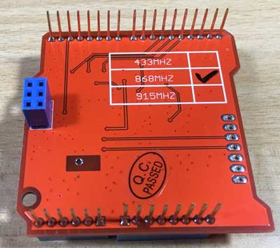
Make the following changes for 868 MHz (LoRa node operating in the Netherlands):
// project-specific definitions
#define CFG_eu868 1
//#define CFG_us915 1
//#define CFG_au915 1
//#define CFG_as923 1
//#define LMIC_COUNTRY_CODE LMIC_COUNTRY_CODE_JP /* for as923-JP */
//#define CFG_kr920 1
//#define CFG_in866 1
#define CFG_sx1276_radio 1
//#define LMIC_USE_INTERRUPTS
#define DISABLE_PING
#define DISABLE_BEACONS
- Open Arduino menu: File | Examples | MCCI LoRaWAN LMIC library | ttn_abp
and save this sketch as: ttn_dragino_abp.ino
Note: The ttn_dragino_abp.ino sketch is modified. The modifications are explained below.
The ttn_dragino_abp.ino sketch uses Activation by Personalization (ABP).
ABP is simpler, because it skips the join procedure, but it has some downsides related to security.
- Goto the Things Network Console (https://www.thethingsnetwork.org/)
- Create an Application.
- Register a device.
Note: Let the system generate the Device EUI and App Key.
- After the Device is registered, change its settings.
- In the Device Settings screen, change Activation Method from OTAA to ABP.
- In the Device Overview screen, copy your values to your Arduino sketch:
Device Address (Select MSB):
0x339240AB (Place 0x in front)
Network Session Key (Select MSB):
{ 0x9A, 0x80, 0x48, 0x7E, 0x8F, 0x56, 0xFF, 0x00, 0x5F, 0x4B, 0xE3, 0x93, 0xFA, 0x5B, 0x3F, 0xE5 }
App Session Key (Select MSB):
{ 0xF9, 0x76, 0xAC, 0xCC, 0x55, 0x32, 0xA9, 0x97, 0xAA, 0xAC, 0x68, 0x23, 0x67, 0xEE, 0xA3, 0xC4 }
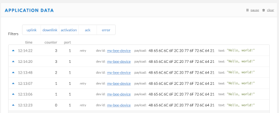
- In TTN console, the "Hello, world!" message (in hex) is received every 20 seconds.
If you want to convert the payload into a readable text, select your application in the "APPLICATION OVERVIEW" screen and select "Payload Formats".
Select "decoder" and paste the
decoder payload format function
in the textbox.
In the bottom of the page press the "save payload function" button.
If you go back to "Data" you will see the payload in human readable text.
- Edit the sketch ttn_dragino_abp.ino:
- Modify NWKSKEY[16], APPSKEY[16] and DEVADDR with correct values. See previous step.
- Change TX_INTERVAL to 20 (Only for test purpose. Watch out for TTN fair use policy regarding uplink airtime).
- Change lmic_pins for Dragino LoRa Shield v1.1 to:
const lmic_pinmap lmic_pins = {
.nss = 10,
.rxtx = LMIC_UNUSED_PIN,
.rst = 9,
.dio = {2, 6, 7},
};
- Add the line:
// Let LMIC compensate for +/- 0.5% clock error
LMIC_setClockError(MAX_CLOCK_ERROR * 0.5 / 100);
... above the line "do_send(&sendjob);"
This line is needed because the sketch will stop running after 1 to 30 minutes and the following error is displayed:
../Documents/Arduino/libraries/MCCI_LoRaWAN_LMIC_library/src/lmic/radio.c:1065
The value 0.5 has been empirical chosen. I tried:
1, 2, 3, 4, 5, 0.9, 0.8, 0.7, 0.6
All these values resulted that the sketch stops running after 1 to 30 minutes.
If the value is 0.5 the sketch will not stop running. I have tested this by running the sketch for 1 hour.
- To test the downlink, the following code is added to the sketch:
if (LMIC.dataLen == 1) {
uint8_t result = LMIC.frame[LMIC.dataBeg + 0];
if (result == 0) {
Serial.println("RESULT 0");
}
if (result == 1) {
Serial.println("RESULT 1");
}
if (result == 2) {
Serial.println("RESULT 2");
}
if (result == 3) {
Serial.println("RESULT 3");
}
}
- Open the TTN console and reset the frame counter.
For test purposes, it is recommended to disable "Frame Counter Checks" in the TTN console "Device Settings" instead of resetting the frame counter.
- Open Arduino menu: Tools
Select Board: "Arduino Uno"
Select: YOUR CORRECT PORT
- Open Arduino menu: Tools | Serial Monitor
Select: 115200 baud
- Upload the sketch to Arduino Uno.
- After the sketch is uploaded, reset the Dragino LoRa shield by pressing the reset button on the Arduino Uno.
The Arduino Uno reset button does not seem to reset my Dragino LoRa shield v1.1.
I have no idea why this is!
To reset my Dragino LoRa shield I always pull and insert the USB cable back again.
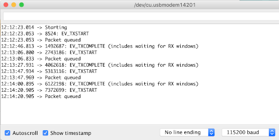
- Test UPLINK
Open the TTN console and check if you see the transmitted "Hello, world!" message.
It is recommended to open the serial monitor to see error/log messages.
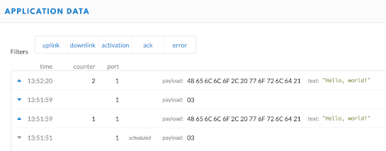
TTN console
Arduino Uno serial monitor
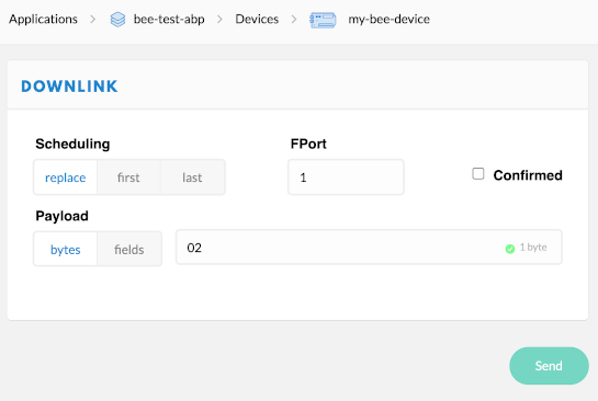
- Test DOWNLINK
In the TTN console, select your device.
In the downlink section enter a hex value (00, 01, 02 or 03) and press the Send button.
In this example the hex value 02 is transmitted.
TTN device downlink section
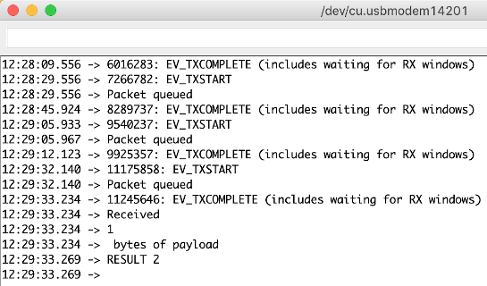
Receive the downlink message in the serial monitor
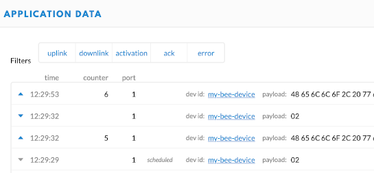
TTN console transmitted downlink message
- Open Arduino menu: File | Examples | MCCI LoRaWAN LMIC library | ttn_otaa
and save this sketch as: ttn_dragino_otaa.ino
Note: The ttn_dragino_otaa.ino sketch is modified. The modifications are explained below.
The ttn_dragino_otaa.ino sketch uses Over-the-Air Activation (OTAA).
OTAA is the preferred and most secure way to connect with The Things Network.
Devices perform a join-procedure with the network, during which a dynamic DevAddr is assigned and security keys are negotiated with the device.
- Goto the Things Network Console (https://www.thethingsnetwork.org/)
- Create an Application.
- Register a device.
Note: Let the system generate the Device EUI and App Key.
- The device must use the default Activation Method: OTAA
In the Device Overview screen, copy your values to your Arduino sketch:
APPEUI (Select LSB):
{ 0x20, 0x11, 0x05, 0xA4, 0x8A, 0xB7, 0xC1, 0x00 }
DEVEUI (Select LSB):
{ 0x5E, 0x1C, 0x56, 0x10, 0x33, 0xCC, 0x89, 0x11 }
APPKEY (Select MSB):
{ 0xAB, 0x55, 0x32, 0x81, 0x89, 0x5A, 0xB0, 0xCC, 0x3E, 0x89, 0xCC, 0x9A, 0x3A, 0xCC, 0xE7, 0x49 }
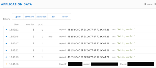
- In TTN console, the "Hello, world!" message (in hex) is received every 20 seconds.
If you want to convert the payload into a readable text, select your application in the "APPLICATION OVERVIEW" screen and select "Payload Formats".
Select "decoder" and paste the
decoder payload format function
in the textbox.
In the bottom of the page press the "save payload function" button.
If you go back to "Data" you will see the payload in human readable text.
- Edit the sketch ttn_dragino_otaa.ino:
- Modify APPEUI[8], DEVEUI[8] and APPKEY[16] with correct values. See previous step.
- Change TX_INTERVAL to 20 (Only for test purpose. Watch out for TTN fair use policy regarding uplink airtime).
- Change lmic_pins for Dragino LoRa Shield v1.1 to:
const lmic_pinmap lmic_pins = {
.nss = 10,
.rxtx = LMIC_UNUSED_PIN,
.rst = 9,
.dio = {2, 6, 7},
};
- Add the line:
// Let LMIC compensate for +/- 0.5% clock error
LMIC_setClockError(MAX_CLOCK_ERROR * 0.5 / 100);
... above the line "do_send(&sendjob);"
This line is needed because the sketch will stop running after 1 to 30 minutes and the following error is displayed:
../Documents/Arduino/libraries/MCCI_LoRaWAN_LMIC_library/src/lmic/radio.c:1065
The value 0.5 has been empirical chosen. I tried:
1, 2, 3, 4, 5, 0.9, 0.8, 0.7, 0.6
All these values resulted that the sketch stops running after 1 to 30 minutes.
If the value is 0.5 the sketch will not stop running. I have tested this by running the sketch for 1 hour.
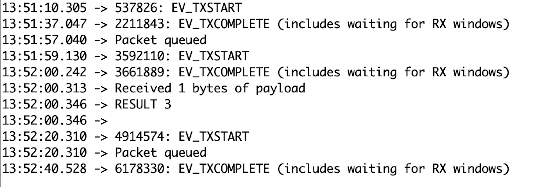
- To test the downlink, the following code is added to the sketch:
if (LMIC.dataLen == 1) {
uint8_t result = LMIC.frame[LMIC.dataBeg + 0];
if (result == 0) {
Serial.println("RESULT 0");
}
if (result == 1) {
Serial.println("RESULT 1");
}
if (result == 2) {
Serial.println("RESULT 2");
}
if (result == 3) {
Serial.println("RESULT 3");
}
}
- Open the TTN console and reset the frame counter.
For test purposes, it is recommended to disable "Frame Counter Checks" in the TTN console "Device Settings" instead of resetting the frame counter.
- Open Arduino menu: Tools
Select Board: "Arduino Uno"
Select: YOUR CORRECT PORT
- Open Arduino menu: Tools | Serial Monitor
Select: 9600 baud
- Upload the sketch to Arduino Uno.
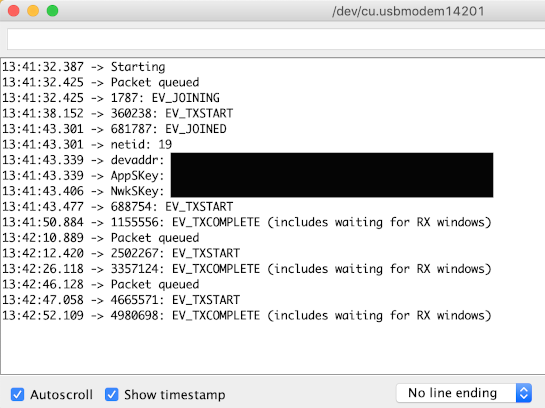
Pay attention to the Arduino IDE logging:
Global variables use 1549 bytes (75%) of dynamic memory, leaving 499 bytes for local variables. Maximum is 2048 bytes.
Low memory available, stability problems may occur.
- After the sketch is uploaded, reset the Dragino LoRa shield by pressing the reset button on the Arduino Uno.
The Arduino Uno reset button does not seem to reset my Dragino LoRa shield v1.1.
I have no idea why this is!
To reset my Dragino LoRa shield I always pull and insert the USB cable back again.
- Test UPLINK
Open the TTN console and check if you see the transmitted "Hello, world!" message.
It is recommended to open the serial monitor to see error/log messages.
TTN console
Arduino Uno serial monitor
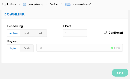
- Test DOWNLINK
In the TTN console, select your device.
In the downlink section enter a hex value (00, 01, 02 or 03) and press the Send button.
In this example the hex value 03 is transmitted.
TTN device downlink section
Receive the downlink message in the serial monitor
TTN console transmitted downlink message
|