Build LoRa node using Arduino Pro Mini and HopeRF RFM95 LoRa transceiver module (V2)
Information
none
Operating system used
macOS Sierra
Hardware used
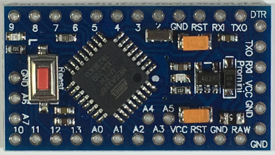
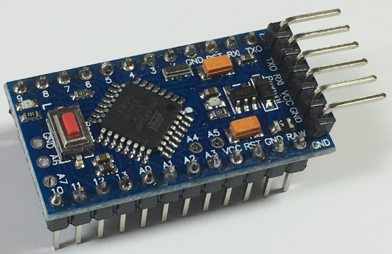
- Arduino Pro Mini (ATmega328P / 3.3V / 8 MHz)
The Arduino Pro Mini: ATmega168 will not work because there is not enough space.
I am not using the Arduino Pro Mini ATmega328P / 5V / 16 MHz because the HopeRF RFM95 LoRa transceiver module uses 3.3V.
Top view.
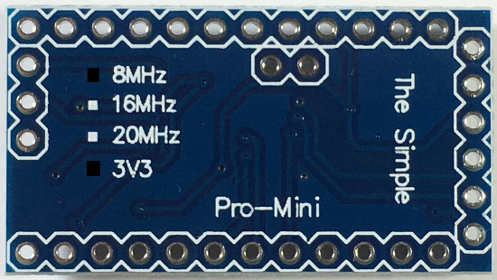
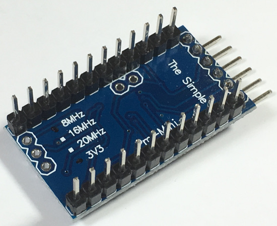
Bottom view.
With the male pin headers soldered.
With the male pin headers soldered, bottom view.
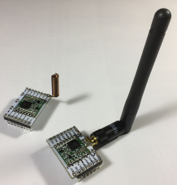
- LoRa module with dipole antenna.
How this is made see tutorial:
Modify ESP8266 module adapter plate for HopeRF RFM95 LoRa transceiver module with RP SMA female edge mount connector
- FTDI FT232RL 3.3/5V
The Arduino Pro Mini does not have an USB connector. To communicate with the Arduino Pro Mini with your computer via an USB port an USB to TTL serial adapter is needed. In this tutorial I will be using the FTDI FT232RL adapter.
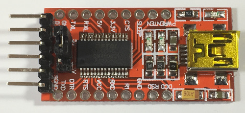
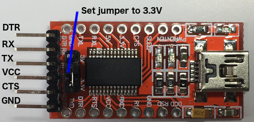
Top view.
Make sure the jumper is set to 3.3V.
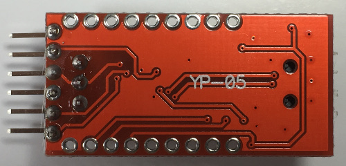
Bottom view.
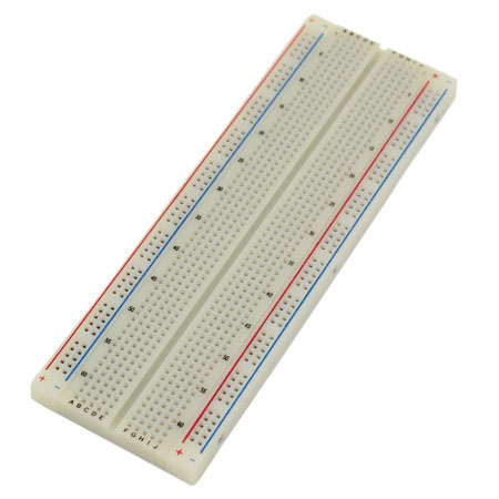
- Breadboard MB-102
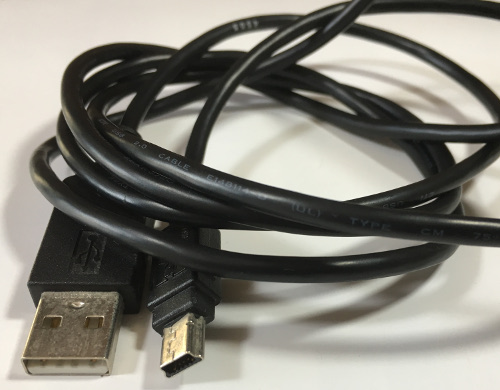
- USB 2.0 cable, USB-A > Mini USB-B (length: 80 cm)
This cable transfers the sketch from computer to the FTDI adapter.
- Jumper wires 15 cm long (6x female-female)
To connect the FTDI adapter to the Arduino Pro Mini.
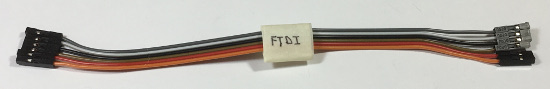
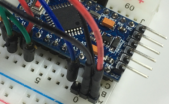
Connect Arduino Pro Mini and FTDI adapter with the FTDI cable.
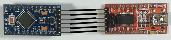
| DTR |
DTR |
| TXO |
RX |
| RXI |
TX |
| VCC |
VCC |
| GND |
CTS |
| GND |
GND |
- Jumper wires 20 cm long (9x male-male)
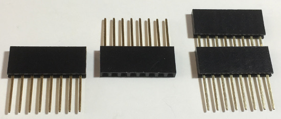
- Female pin headers 8 pins (4 pcs)
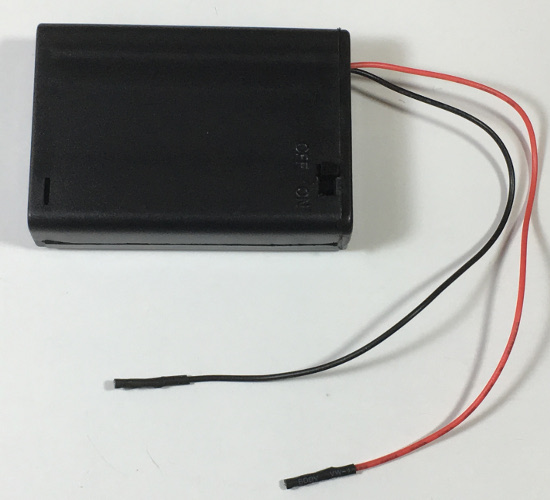
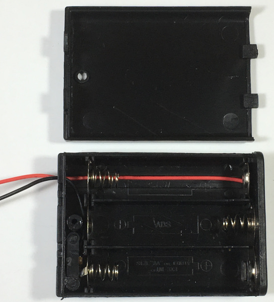
- Battery holder 3x1.5=4.5V (3x AA)
Battery holder open.
Software prerequisites
none
Procedure
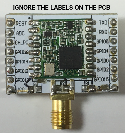
- The HopeRF RFM95 LoRa transceiver module.
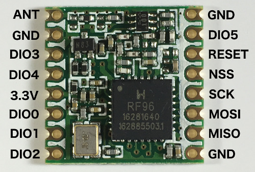
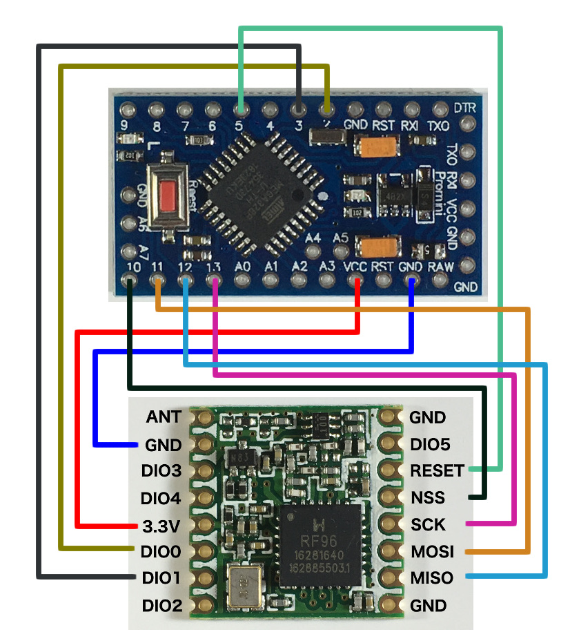
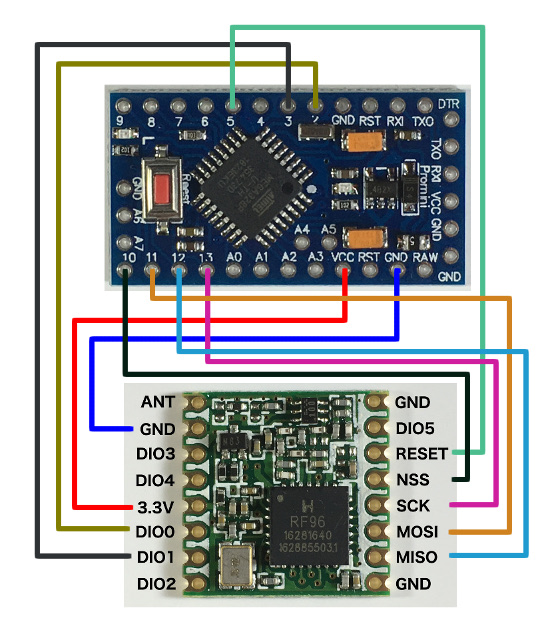
Make the following jumper wire connections between the HopeRF RFM95 LoRa transceiver module and the Arduino Pro Mini.
|
ANT
|
-
|
GND
|
-
|
|
GND
|
GND
|
DIO5
|
-
|
|
DIO3
|
-
|
RESET
|
5
|
|
DIO4
|
-
|
NSS
|
10
|
|
3.3V
|
VCC
|
SCK
|
13
|
|
DIO0
|
2
|
MOSI
|
11
|
|
DIO1
|
3
|
MISO
|
12
|
|
DIO2
|
-
|
GND
|
-
|
ANT = Antenna
GND = Ground
DIO = Digital Input/Output
NSS = Slave Select
SCK = Serial Clock (output from master)
MOSI = Master Out Slave In (data output from master)
MISO = Master In Slave Out (data output from slave)
Note:
- Always attach the dipole antenna to the SMA connector BEFORE powering up the LoRa module otherwise you may damage the HopeRF RFM95 LoRa transceiver module.
- The HopeRF RFM95 LoRa transceiver module has 3 GND pins.
Use the GND pin below the Antenna pin.
- Do not use DIO2, DIO3, DIO4 and DIO5.
- The Arduino Pro Mini uses SPI (Serial Peripheral Interface) to communicate with the HopeRF RFM95 LoRa transceiver module.
The Arduino Pro Mini is the Master and the HopeRF RFM95 LoRa transceiver module is the Slave.
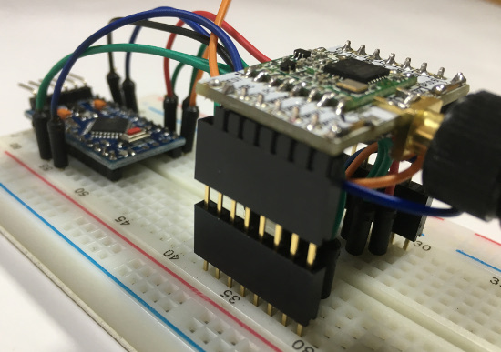
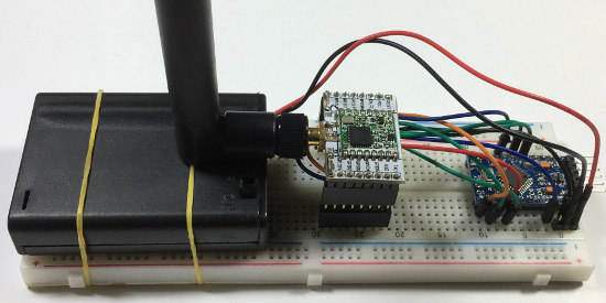
Wiring HopeRF RFM95 LoRa transceiver module and Arduino Pro Mini.
Click on the image for a larger image.
Wiring LoRa module and Arduino Pro Mini.
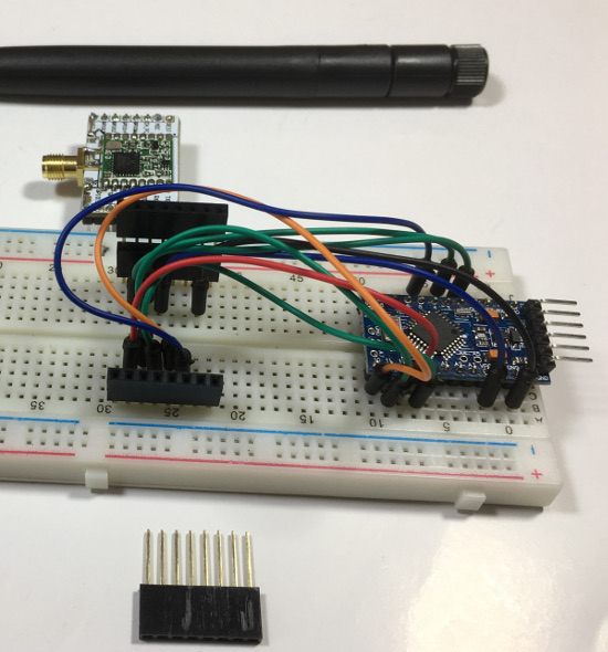
Stack two female pin headers (2x) and place them on the breadboard with the LoRa module on top.
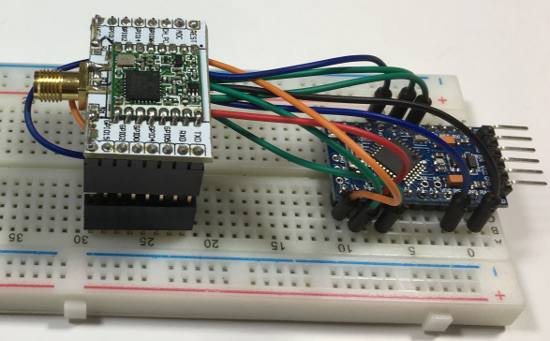
Attach dipole antenna.
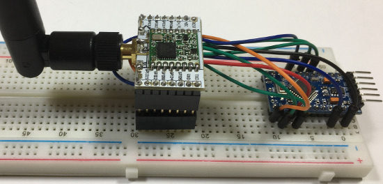
Side view.
- Make sure a LoRa gateway is in your area and the LoRa node can send messages to that gateway.
Use this map: https://www.thethingsnetwork.org/map
- Install the latest open source Arduino IDE.
https://www.arduino.cc/en/Main/Software
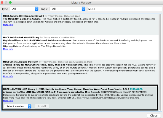
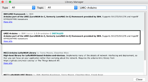
- Now install the MCCI LoRaWAN LMIC Library.
- In the Arduino IDE, select menu Sketch | Include Library | Manage Libraries
- In the search box enter: MCCI
- Click the MCCI LoRaWAN LMIC Library.
- Select the latest version and press the Install button.
- Configure the MCCI LoRaWAN LMIC Library according to your situation.
Edit file lmic_project_config.h. This file can be found at:
../libraries/MCCI_LoRaWAN_LMIC_library/project_config
I made the following changes to MY lmic_project_config.h file.
Make changes according to YOUR situation.
// project-specific definitions
#define CFG_eu868 1
//#define CFG_us915 1
//#define CFG_au921 1
//#define CFG_as923 1
//#define LMIC_COUNTRY_CODE LMIC_COUNTRY_CODE_JP /* for as923-JP */
//#define CFG_in866 1
#define CFG_sx1276_radio 1
//#define CFG_sx1272_radio 1
#define DISABLE_PING
#define DISABLE_BEACONS
#define LMIC_DEBUG_LEVEL 0
#define USE_IDEETRON_AES
- Create an account on The Things Network (TTN), add an application and register a device.
Make sure the activation method is OTAA.
- In the Arduino IDE, select menu File | Examples | MCC LoRaWAN LMIC library and select the ttn-otaa sketch.
Re-save the ttn-otaa sketch and call it ttn-otaa-helloworld.
From The Things Network console copy YOUR DevEUI, AppEUI and AppKey to the ttn-otaa-helloworld sketch.
Watch out:
The DevEUI and AppEUI must be in little-endian format.
The AppKey must be in big endian format
- Modify the ttn-otaa-helloworld sketch.
// Pin mapping
const lmic_pinmap lmic_pins = {
.nss = 10,
.rxtx = LMIC_UNUSED_PIN,
.rst = 5,
.dio = {2, 3, LMIC_UNUSED_PIN},
};
- The Arduino Pro mini is running at 8MHz and is relatively slow for LMIC and needs an adjustment by relaxing the timing.
Add the line: LMIC_setClockError(MAX_CLOCK_ERROR * 1 / 100);
in the setup function, between the LMIC_Reset() and the do_send(&sendjob).
It makes the receive windows bigger, in case the clock is 1% faster or slower.
In the ttn-otaa-helloworld sketch, I added the above mentioned line in the setup function.
See the red marked lines:
void setup() {
Serial.begin(9600);
Serial.println(F("Starting"));
#ifdef VCC_ENABLE
// For Pinoccio Scout boards
pinMode(VCC_ENABLE, OUTPUT);
digitalWrite(VCC_ENABLE, HIGH);
delay(1000);
#endif
// LMIC init
os_init();
// Reset the MAC state. Session and pending data transfers will be discarded.
LMIC_reset();
// Use with Arduino Pro Mini ATmega328P 3.3V 8 MHz
// Let LMIC compensate for +/- 1% clock error
LMIC_setClockError(MAX_CLOCK_ERROR * 1 / 100);
// Start job (sending automatically starts OTAA too)
do_send(&sendjob);
}
Here is the final sketch: ttn-otaa-helloworld.ino.
- In this sketch the message "Hello, world!” will be transmitted every 60 seconds, see variables: mydata[] and TX_INTERVAL.
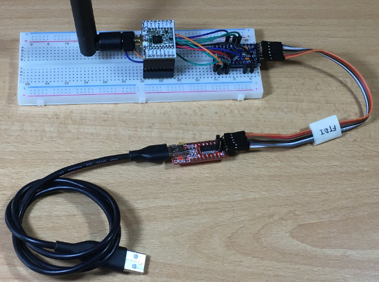
- Connect the Arduino Pro Mini to your computer using the USB cable and FTDI adapter.
- In the Arduino IDE, select menu Tools | Board and select: Arduino Pro or Pro Mini
In the Arduino IDE, select menu Tools | Processor: ATmega328P (3.3V, 8MHz)
In the Arduino IDE, select menu Tools | Port: your port
- Compile ttn-otaa-mydemo sketch.
You should not see any errors.
- Upload the ttn-otaa-mydemo sketch to the Arduino Pro Mini.
You should not see any errors.
- In TTN console, the "Hello, world!" message (in hex) is received every 60 seconds.
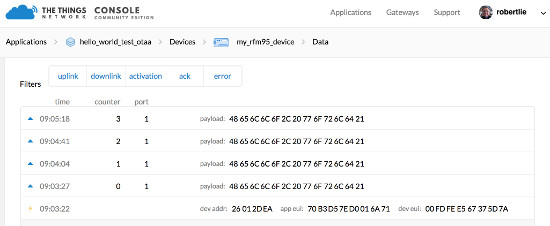
If you want to convert the payload into a readable text, select your application and in the "APPLICATION OVERVIEW" screen and select "Payload Formats".
Select "decoder" and paste the
decoder payload format function
in the textbox.
In the bottom of the page press the "save payload function" button.
If you go back to "Data" you will see the payload in human readable text.
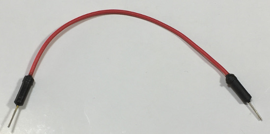
- The Arduino Pro Mini can be powered by 3x AA (1.5V) batteries.
Disconnect the FTDI jumper wires from the Arduino Pro Mini and connect the battery holder.
|
RAW
|
+ (red wire)
|
|
GND
|
- (black wire)
|
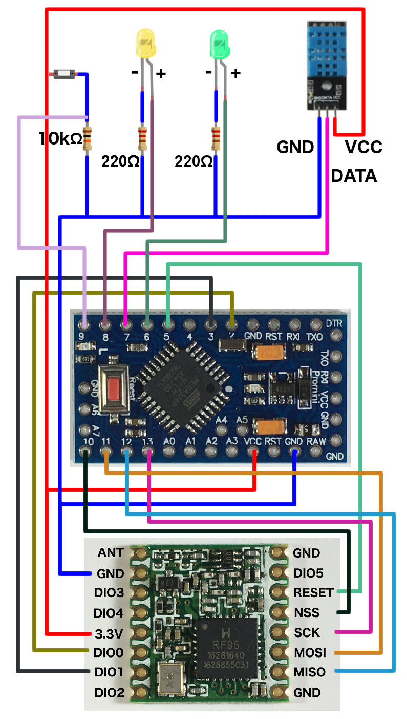
- Optionally a push button, 2 LEDs and a DHT11 sensor can be added.
Click on the image for a larger image.

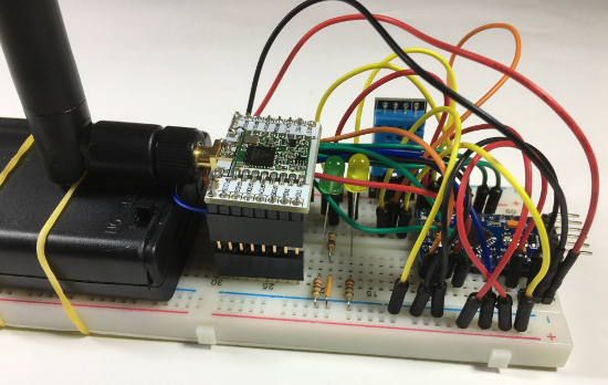
The sketch for this circuit diagram: ttn-otaa-pro-mini-sensors.ino.
For this sketch, to make the payload data more human readable in TTN console, select tab "Payload Formats", select decode and copy and paste the decoder function from this link
tutorial_26_decoder.txt and paste it in this field.
The sketch behaves the same as discussed in LoRa/LoRaWAN tutorial 26, see:LoRa/LoRaWAN tutorial
- Optionally an OLED display can be added.
Hardware used:
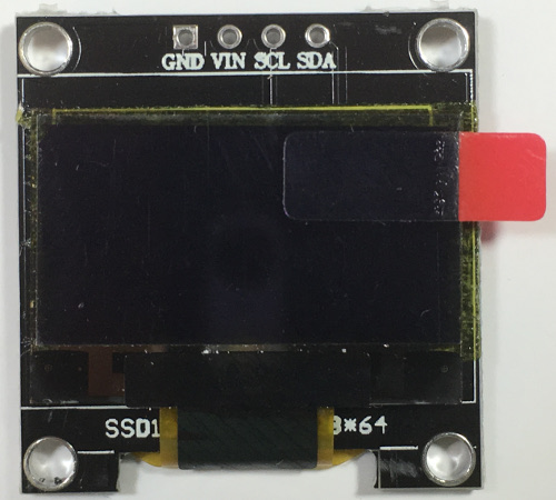
0.96" (128x64) I2C White OLED display module SSD1306 (3V ~ 5V DC)
Note: I have the left the protective cover on (protect the OLED display during shipment).
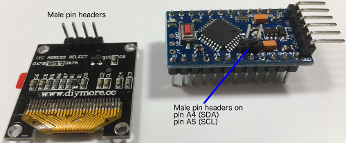
Solder male pin headers on the OLED display module and Arduino Pro Mini.
Make the following jumper wire connections between the OLED display module and the Arduino Pro Mini.
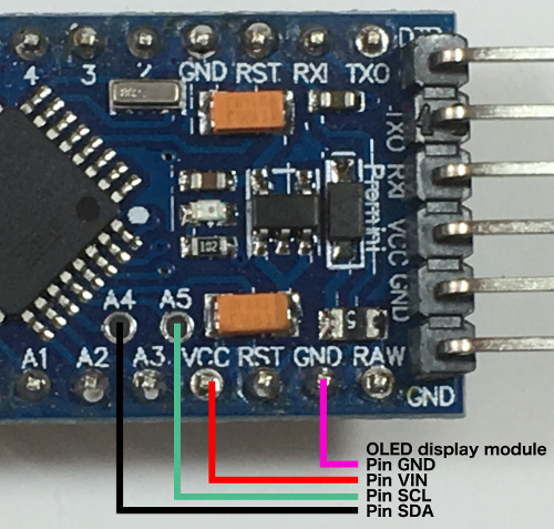
| VCC (3.3V output) |
VIN |
| GND |
GND |
| A4 (SDA, Serial Data) |
SDA |
| A5 (SCL, Serial Clock) |
SCL |
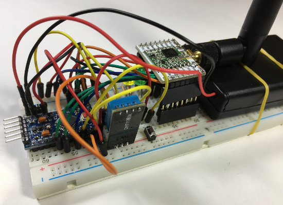
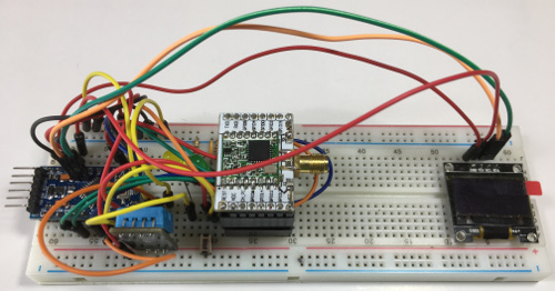
Arduino Pro Mini, LoRa module without antenna, sensors and OLED display module.
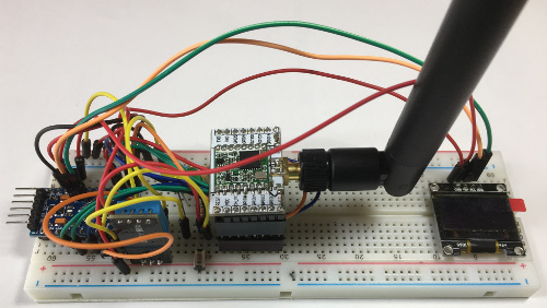
Arduino Pro Mini, LoRa module with antenna, sensors and OLED display module.
- For the OLED display module the SSD1306Ascii library will be used.
This Arduino library displays texts on small monochrome OLED modules (SSD1306).
It only displays texts and is optimised for minimum memory usage.
More information:
https://github.com/greiman/SSD1306Ascii/
The updated sketch working with the 0.96" OLED display module:
lmic-ttn-otaa-pro-mini-sensors-oled.ino
This sketch ONLY works using the following libraries:
- LMIC-Arduino (It does not work with the MCCI LoRaWAN LMIC Library)
Remove the already installed MCCI LoRaWAN LMIC Library!
Use the Library Manager and install the LMIC-Arduino library.
Configure the LMIC-Arduino library according to your situation.
Edit file config.h. This file can be found at:
../libraries/arduino-lmic/src/lmic
I made the following changes to MY config.h file.
Make changes according to YOUR situation.
#ifndef _lmic_config_h_
#define _lmic_config_h_
#define CFG_eu868 1
#define CFG_sx1276_radio 1
#define US_PER_OSTICK_EXPONENT 4
#define US_PER_OSTICK (1 << US_PER_OSTICK_EXPONENT)
#define OSTICKS_PER_SEC (1000000 / US_PER_OSTICK)
#define LMIC_DEBUG_LEVEL 0
#define LMIC_FAILURE_TO Serial
#define USE_IDEETRON_AES
#endif
Note 1:
If you use the MCCI LoRaWAN LMIC library together with the SSD1306Ascii library the sketch will be too large to fit in the program storage.
That is why I use the LMIC-Arduino library.
Note 2:
The sketch also contains code that makes the yellow led blink during the joining procedure.
If the device is joined the blinking stops.
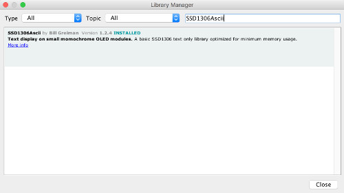
- SSD1306Ascii
Use the Library Manager and install the SSD1306Ascii library.
Note 1: I have made no changes to the SSD1306Ascii library.
Note 2: I tried using Adafruit libraries adafruit_GFX and
adafruit_SSD1306 in the sketch lmic-ttn-otaa-pro-mini-sensors-oled.ino but
these libraries together with the other libraries (lmic.h, hal.h, SPI.h, DHT.h, DHT_U.h and Adafruit_Sensor.h) makes the sketch too large to fit in the program storage.
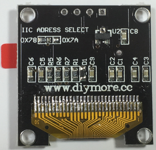
Note 3: On the backside of OLED display module:
If address 0x78 is used then in the lmic-ttn-otaa-pro-mini-sensors-oled.ino sketch use:
#define I2C_ADDRESS 0x3C (My situation)
If address 0x7A is used then in the lmic-ttn-otaa-pro-mini-sensors-oled.ino sketch use:
#define I2C_ADDRESS 0x3D
|