LoRaWAN (Long Range Wide Area Network) is a specification for a telecommunication network suitable for long-distance communication with little power.
The technology is used for machine-to-machine communication (Internet of Things).
The architecture consists of gateways, network servers and application servers. There are RF chips from Semtech used to transmit a spread spectrum.
Build Lora module using ESP8266 module adapter plate, RFM95 LoRa transceiver module with RP SMA female edge mount connector
Information
none
Operating system used
none
Hardware used
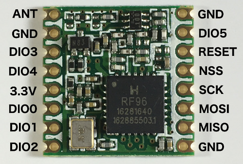
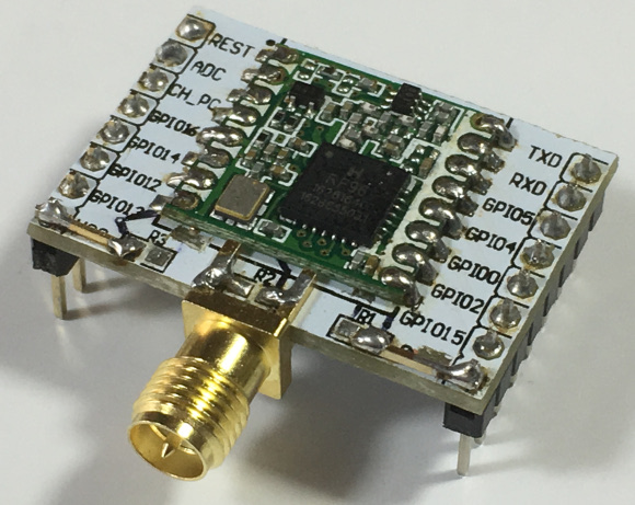
The HopeRF RFM95 LoRa transceiver module is marked RF96 which means the chip is using the SX1276 chip.
The RFM95 and RFM95W are the same.
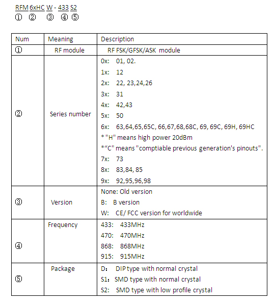
W=CE/FCC version for worldwide, without W=internal Chinese market only.
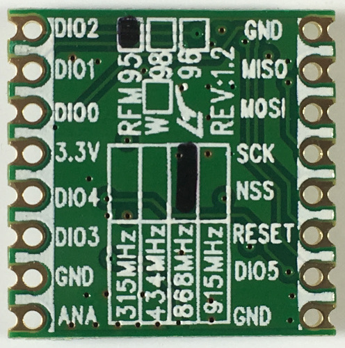
Bottom view. The frequency used in Europe is 868 MHz, for North America 915 MHz and for Asia 433 MHz. Make sure your HopeRF RFM95 LoRa transceiver module has the correct frequency.
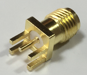
RP SMA female edge mount connector.
I have used a RP SMA female connector because my antenna has a RP SMA male connector.
Choose a SMA connector which applies to your situation!
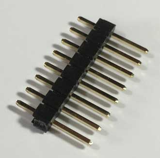
Breakable male pin headers (1 strip with 8 pins and 1 strip with 7 pins)
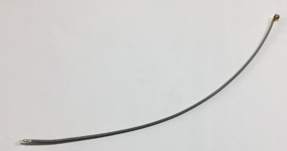
U.FL IPX IPEX 1.13mm RF pigtail coaxial jumper cable for antenna WiFi (length 150 mm).
I only needed 30 mm of this cable.
Software prerequisites
none
Procedure
Cut the ESP8266 module adapter plate (this is optional) and remove the resistors as shown in the video.
Do not solder the pin headers yet! Stop watching the video at time stamp 5:16.
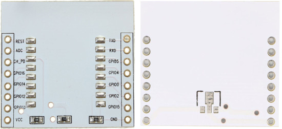
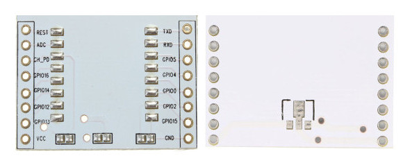
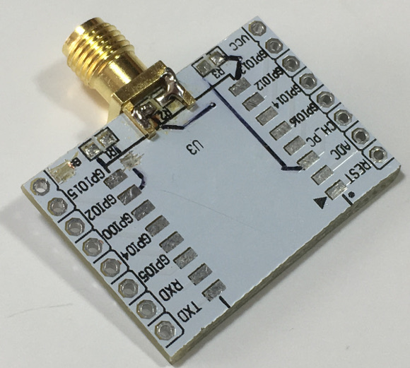
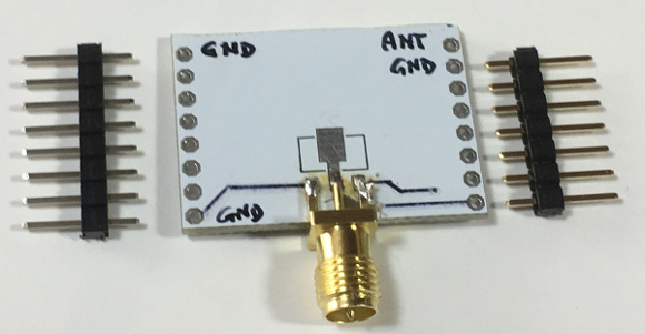
The ESP8266 module adapter plate cut (this is optional) and without the resistors.
Use a multimeter and check all the PCB traces.
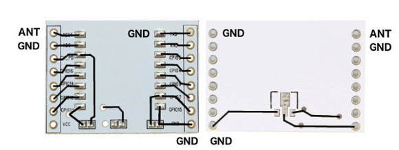
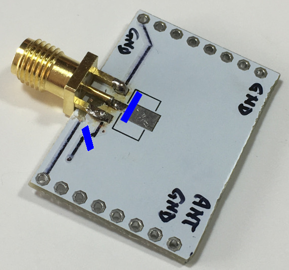
I have marked the LoRa module ANTENNA (ANT) and GROUND (GND) location.
IF YOU MAKE A MISTAKE, YOU CAN DAMAGE YOUR HOPERF RFM95 LORA TRANSCEIVER MODULE.
I CAN NOT GUARANTEE THESE PCB TRACES ARE EXACTLY THE SAME FOR YOUR SITUATION.
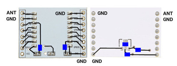
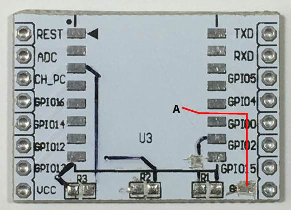
Use a Stanley knife a remove the blue marked PCB traces as indicated in the picture.
The PCB trace is approx. 0.4 mm below the plate surface.
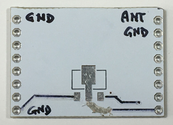
Here are a few pictures with the PCB trace cut. Not completely done.
Oeps, in the bottom right corner (A) I mistakenly removed the PCB trace! Luckily I can easily fixed it by adding a wire connection.
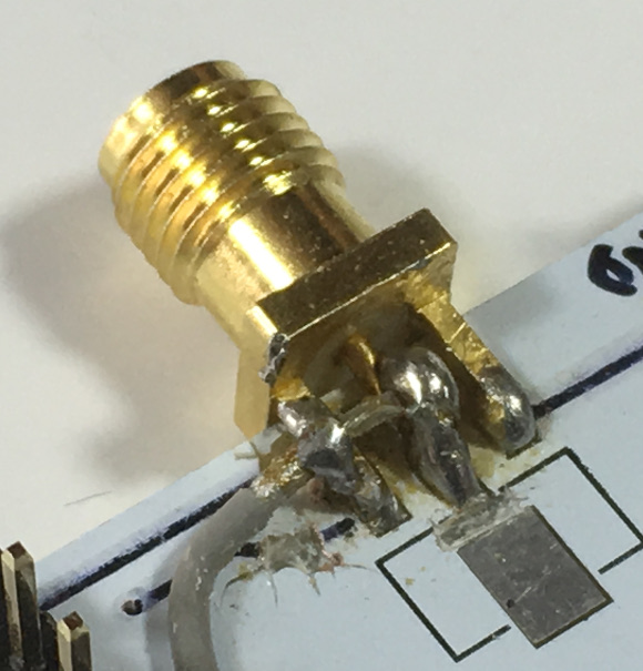
Solder the RP SMA female edge mount connector.
Solder the three pins on the bottom side.
I should have removed the blue marked PCB traces, unfortunately I have done this later!
Solder the RP SMA female edge mount connector on the top side.
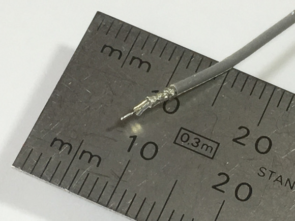
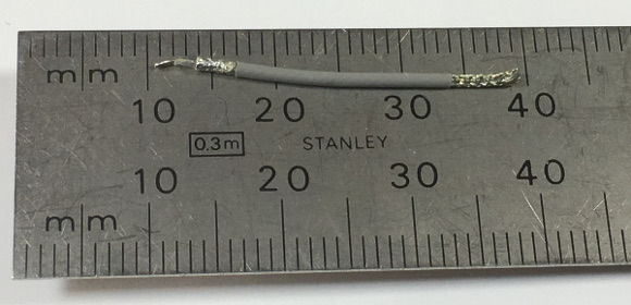
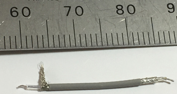
Cut 30 mm off the pigtail coaxial cable and remove 5 mm off the jacket.
You will see the copper braid, see picture right side.
On the left side the cable was already good. Use the picture to estimate where to cut.
Separate the braid and cut 2-3 mm off the dielectric which will expose the center conductor.
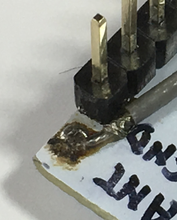
Prepare the pin headers. One strip has 8 pins (left) and the other has 7 pins (right).
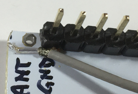
Insert the center conductor and the braid in their corresponding PCB hole BEFORE soldering the pin header.
In the picture below I regretted that I had not inserted the center conductor earlier! You learn from your mistakes!
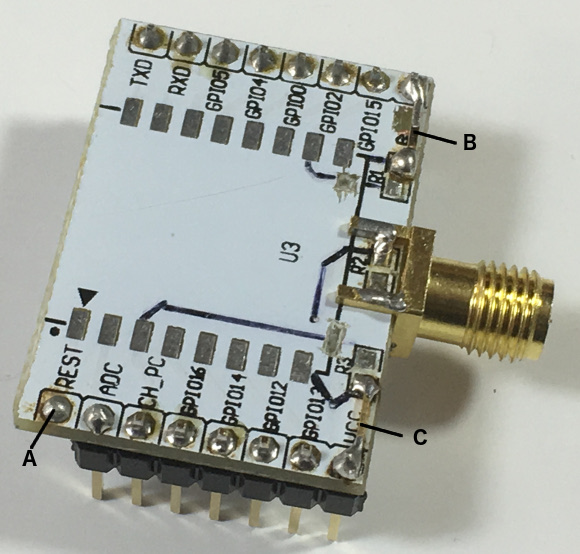
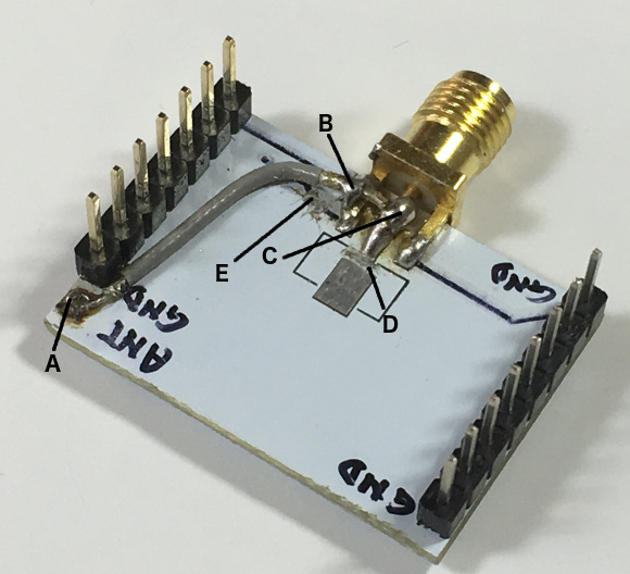
Solder the center conductor on the top side (A).
Solder all pins of both pin headers.
As mentioned earlier I mistakenly removed a PCB trace, this is fixed with wire connection (B).
I have added a wire connection (C) for DIO2 port but it is not really needed as DIO2 is not used.
Solder the coax cable center conductor on the PCB hole (A).
Solder the coax cable braid on the SMA connector mounting pin (B).
Solder the coax cable center conductor on the SMA connector center pin (C).
The PCB trace was removed at D and E. It was better to do this much earlier!
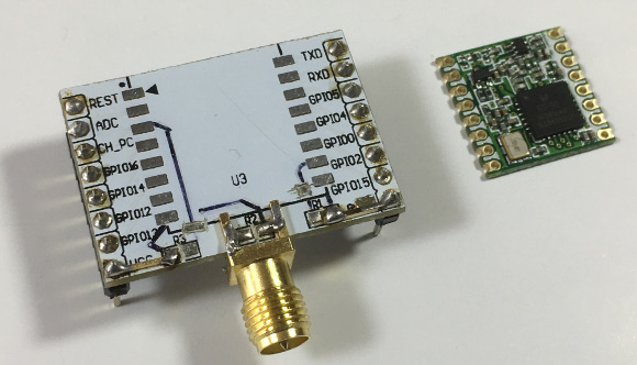
Solder the RFM95 LoRa module on the adapter plate.
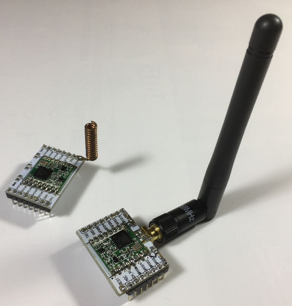
The ESP8266 module adapter plate with RFM95 LoRa module, SMA female edge mount connector and dipole antenna.
For comparison, another LoRa node with a fixed coil antenna directly soldered on the ESP8266 module adapter plate.