IOTA is an open-source distributed ledger. It uses a directed acyclic graph (DAG) instead of a blockchain.
IOTA's DAG is referred to as the tangle, and is a generalization of the block chain protocol.
Send DHT11 sensor data using the Arduino Uno, HopeRF RFM95 LoRa transceiver and The Things Network to IOTA Tangle using Masked Authenticated Messaging (MAM)
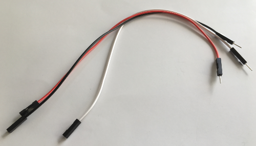
Jumper wires (3x female-male; 20 cm long, 2x male-male; 20 cm long)
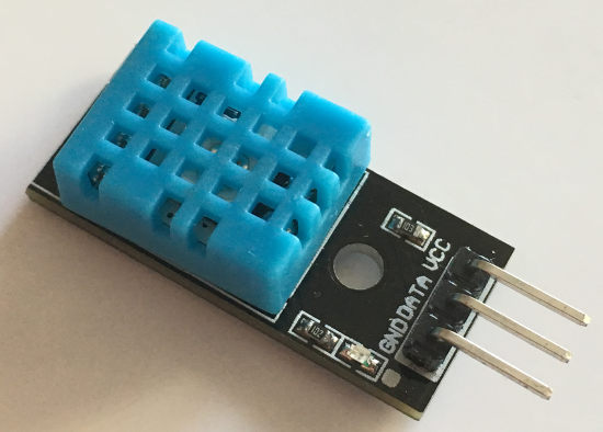
DHT11 sensor module (DHT = Digital Humidity Temperature)
Specification:
Supply voltage: 3.3 ~ 5.5V DC
Output: single-bus digital signal
Measuring range: humidity 20-90% RH, temperature 0 ~ 50°C
Accuracy: humidity ±5% RH, temperature ±2°C
Resolution: Humidity 1% RH, temperature 1°C
Long-term stability: < ±1% RH / Year
Software prerequisites
none
Procedure
Before you start, please note this tutorial was specifically written for macOS users.
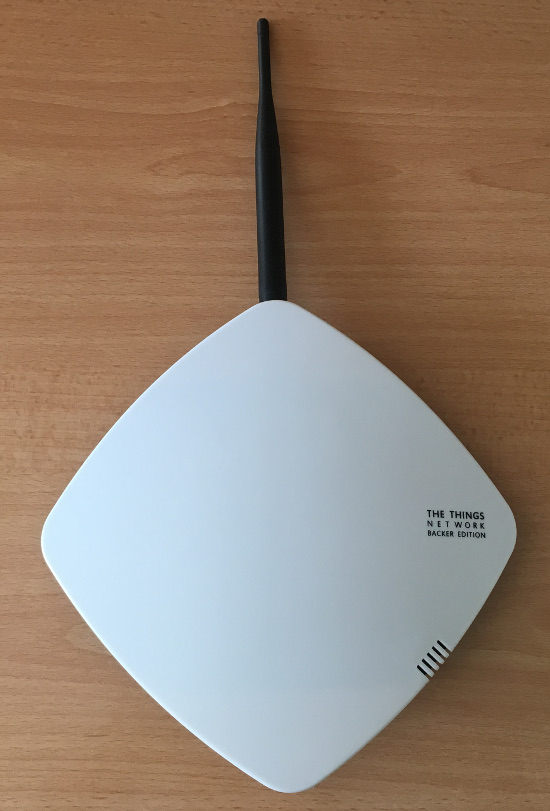
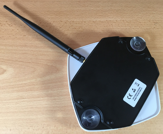
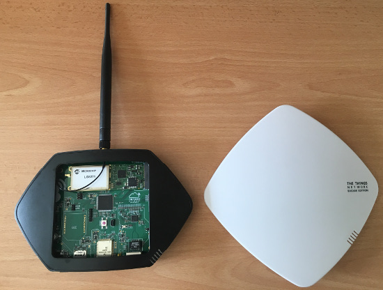
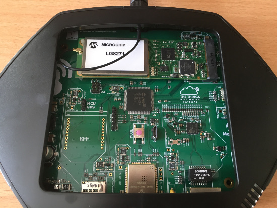
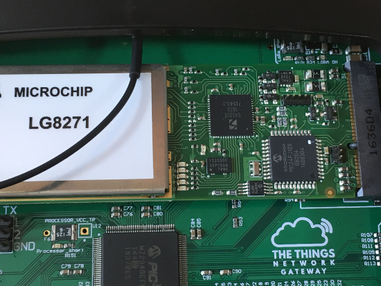
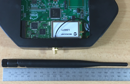
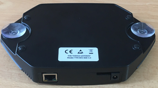
A. I asume you have The Things Gateway and have activated it, see:
Note:
You do not need The Things Gateway (= LoRa Gateway) if there is one nearby and is connected to The Things Network.
To check if a LoRa Gateway is nearby and is connected to The Things Network: https://www.thethingsnetwork.org/map
This LoRa node works on 868mhz. Do not use this LoRa node if your region does not support it, otherwise you break the law!
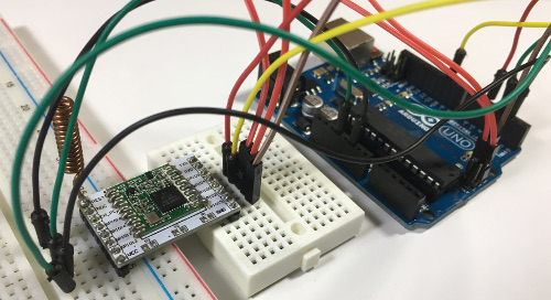
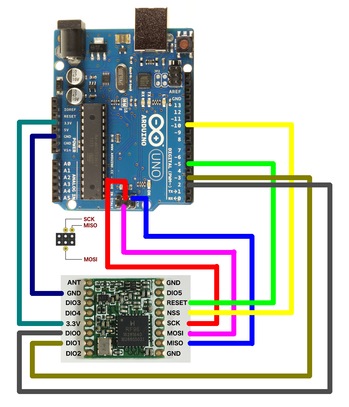
If you have followed step B tutorials you will end up with the HopeRF RFM95 LoRa transceiver module wired to the Arduino Uno (R3) as described in the wiring diagram below:
HopeRF RFM95 LoRa transceiver module
Arduino Uno Pin
HopeRF RFM95 LoRa transceiver module
Arduino Uno Pin
ANT
-
GND
-
GND
GND
DIO5
-
DIO3
-
RESET
5
DIO4
-
NSS
10
3.3V
3.3V
SCK
13
DIO0
2
MOSI
11
DIO1
3
MISO
12
DIO2
-
GND
-
ANT = Antenna
GND = Ground
DIO = Digital Input/Output
NSS = Slave Select
SCK = Serial Clock (output from master)
MOSI = Master Out Slave In (data output from master)
MISO = Master In Slave Out (data output from slave)
Note:
Attach coil antenna to ANT pin.
The HopeRF RFM95 LoRa transceiver module has 3 GND pins.
It does not matter which GND pin you use.
Use at least one.
Do not use DIO2.
The Arduino Uno uses SPI (Serial Peripheral Interface) to communicate with the LoRa transceiver module.
The Arduino Uno is the Master and the LoRa transceiver module is the Slave.
Wiring HopeRF RFM95 LoRa transceiver module and Arduino Uno (R3).
Click on the image for a larger image.
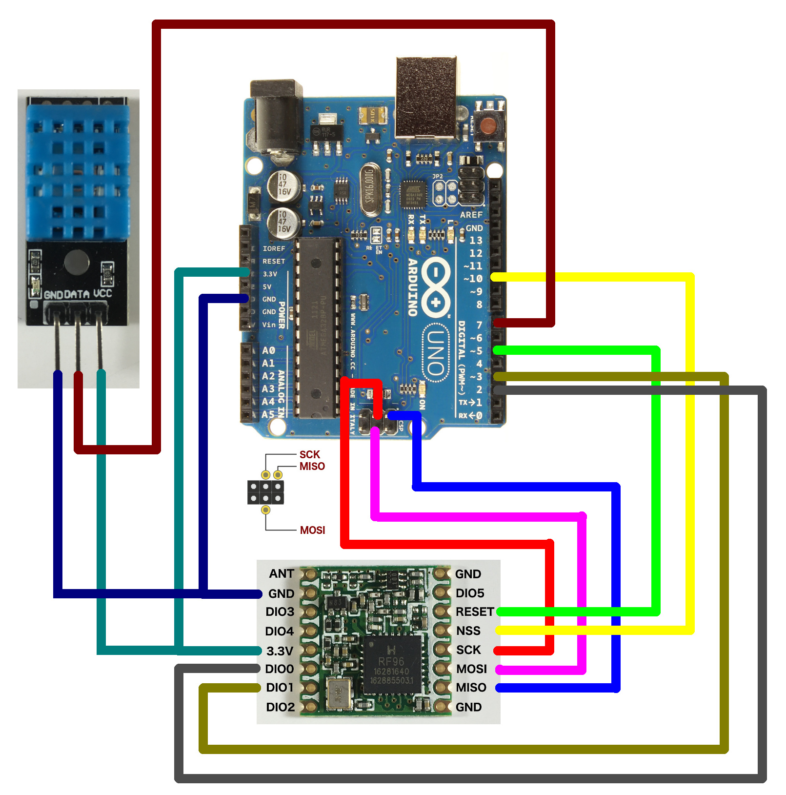
Connect the DHT11 sensor module to the Arduino Uno using the jumper wires.
Arduino Uno
DHT11
GND
GND
pin 7
DATA
3.3V
VCC
Wiring HopeRF RFM95 LoRa transceiver module, Arduino Uno (R3) and DHT11 sensor module.
Click on the image for a larger image.
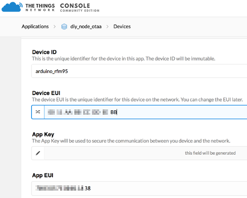
I assume you already have created an account on The Things Network and created an application in the Things Network console (eg: diy_node_otaa).
Here is an example how a device is registered.
Enter the Device ID: arduino_rfm95
Enter Device EUI: 0011AABBCCDDEEBB (arbitrary chosen id)
The App Key and App EUI are auto generated.
Note:
The HopeRF RFM95 LoRa transceiver module has NO hardcoded EUI like the Things Uno.
You just need to enter an arbitrary unique Device EUI, consisting of 16 hex characters (0-9A-F).
Download the dht11-ttn-rfm95 project on your computer:
Type: git clone https://github.com/robertlie/dht11-ttn-rfm95.git
We need to modify the dht11-ttn-rfm95/sketches/ttn-otaa-dht11/ttn-otaa-dht11.ino sketch.
Start Arduino IDE.
Modify the ttn-otaa-dht11.ino sketch, select menu: File > Select the ttn-otaa-dht11.ino file.
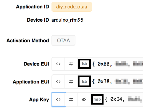
Update the APPEUI, DEVEUI and APPKEY according to your situation.
You can find these values in The Things console (Devices).
For APPEUI and DEVEUI make sure you select lsb (least significant byte first) display.
For APPKEY make sure you select msb (most significant byte first) display.
Use the Arduino IDE Library Manger and install the following libraries:
IBM LMIC framework (by IBM)
DHT sensor library (by Adafruit)
The IBM LMIC framework library is installed in folder (in MacOS):
homedir/Documents/Arduino/libraries/arduino-lmic-master
If you use a HopeRF RFM95 module, set: #define CFG_sx1276_radio 1
If you want logging in the serial monitor, set:
#define LMIC_DEBUG_LEVEL 2
#define LMIC_FAILURE_TO Serial
Uncomment line: #define DISABLE_PING
Disable this feature. It is not needed and space is freed up.
Uncomment line: #define DISABLE_BEACONS
Disable this feature. It is not needed and space is freed up.
Select menu: Tools > Board > Arduino/Genuino Uno
Select the port, select menu: Tools > Port > /dev/cu.usbmodem1421
Note: Your port name may differ.
Press the verify button to verify the sketch. Make sure there are no errors.
Press the upload button to upload the sketch to the Arduino Uno.
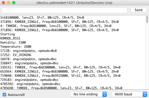
Open the Serial monitor, select menu: Tools > Serial Monitor.
Make sure the baud rate is set to 9600 baud (bottom right)
The temperature and humidity is displayed every 60 second.
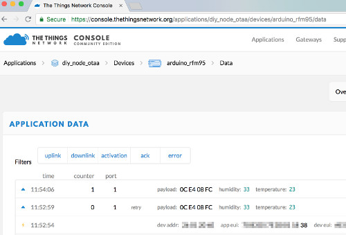
Log into The Things Network console.
Select the correct app and device to see the logged data.
Note:
To display readable data, the following decoder payload function format is used:
function Decoder(bytes, port) {
var humidity = (bytes[0]<<8) | bytes[1];
var temperature = (bytes[2]<<8) | bytes[3];
return {
humidity: humidity/ 100,
temperature: temperature/100
}
}
As demonstrated The Things Network server receives the temperature and humidity data.
Close the serial monitor
Test if the temperature and humidity data can be extracted from The Things Network server using a nodeJS application.
This node application in turn stores the sensor data on the Tangle using Masked Authenticated Messaging.
Open a terminal
Type: cd dht11-ttn-rfm95
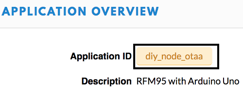
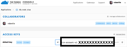
Modify the dht_ttn_mam.js file by entering your appID and accessKey.
The appID can be found here:
The accessKey can be found here:
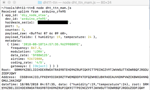
Type: node dht_ttn_mam.js
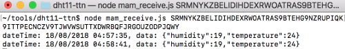
Open another terminal and type: node mam_receive.js your_root
The stored data is displayed.