IOTA is an open-source distributed ledger. It uses a directed acyclic graph (DAG) instead of a blockchain.
IOTA's DAG is referred to as the tangle, and is a generalization of the block chain protocol.
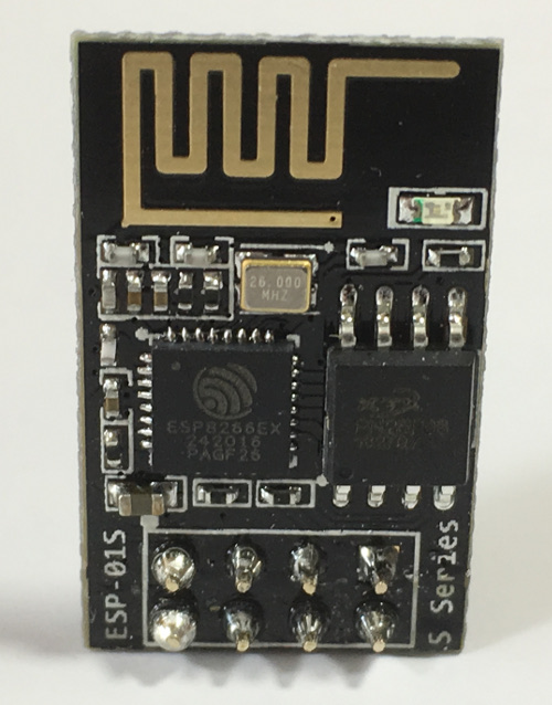
ESP-01S ESP8266 WiFi module
The ESP8266 is a low-cost Wi-Fi chip with full TCP/IP stack and microcontroller capability produced by a Chinese manufacturer, Espressif Systems.
The ESP-01S module, using the ESP8266 WiFi chip, is made by a third-party Chinese manufacturer, AI-Thinker.
AI-Thinker has produced many different ESP8266 modules, ESP-01, ESP-01S, ESP-02, ESP-03, etc.
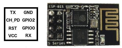
Top view
CH_PD = CHip Pull Down, on my ESP-01S it is marked as EN
VCC = The ESP-01S requires 3.3V input
GPIO0 = On my ESP-01S it is marked as IO0
GPIO2 = On my ESP-01S it is marked as IO2
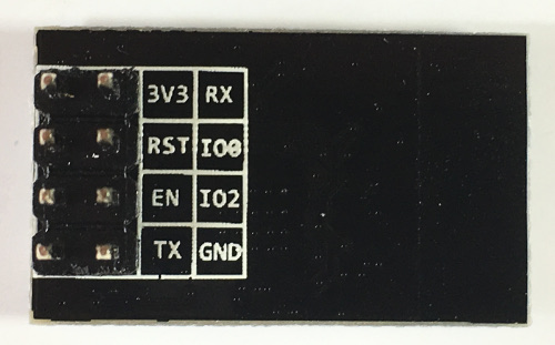
Bottom view
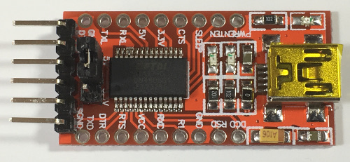
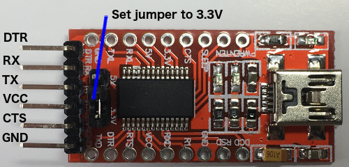
FTDI FT232RL 3.3/5V
The ESP-01S does not have an USB connector. To communicate with the ESP-01S with your computer via an USB port an USB to TTL serial adapter is needed. In this tutorial I will be using the FTDI FT232RL adapter but you can use an Arduino Uno instead, but that method is not described here.
Top view
The VCC pin can output 3.3V or 5.0V depending on how you set the jumper.
However I will NOT use the FTDI VCC pin, the ESP-01S module requires too much current which the FTDI VCC output can not deliver.
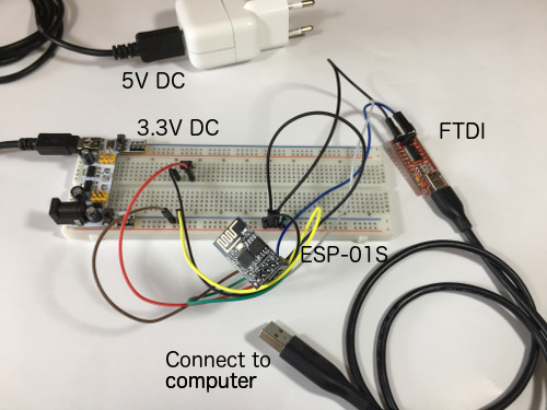
Instead the ESP-01S module will be powered by an external breadboard power supply module.
The FTDI adapter itself is powered (5V) by the USB-A -> mini USB-B cable.
Bottom view
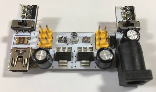
Breadboard MB-102
Breadboard power supply module (2 Channel 3.3V/5V) for MB-102 or half size breadboard
Voltage input: 7-12 V DC
Voltage output: 3.3 / 5 V DC
The breadboard power supply module is used as an external power source for the ESP-01S module.
The ESP-01S module requires too much current which the FTDI VCC output can not deliver.
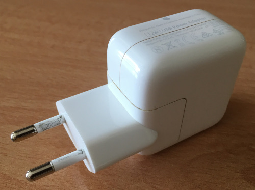
Mobile phone charger (Output: 5.2 V DC, 2.4 A)
The mobile phone charger provides power to the breadboard power supply module.
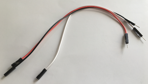
Jumper wires (10x female-male; 20 cm long, 2x female-female, 20 cm long; 2x male-male, 20 cm long)
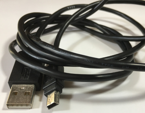
USB 2.0 cable, USB-A > Mini USB-B
You need 2 cables, one for the mobile phone charger (length: 1.5 m) and the other for the FTDI adapter (length: 80 cm)
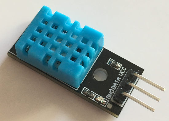
DHT11 sensor module (DHT = Digital Humidity Temperature)
Specification:
Supply voltage: 3.3 ~ 5.5V DC
Output: single-bus digital signal
Measuring range: humidity 20-90% RH, temperature 0 ~ 50°C
Accuracy: humidity ±5% RH, temperature ±2°C
Resolution: Humidity 1% RH, temperature 1°C
Long-term stability: < ±1% RH / Year
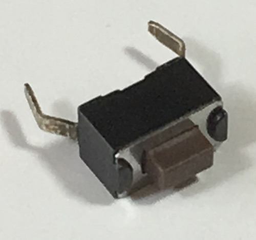
Push button (pitch 2.54 mm, to be used on breadboard)
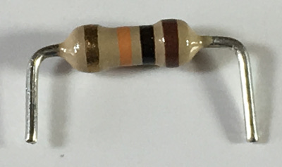
10 kΩ resistor
Used as pull up on the DHT11 data line.
Software prerequisites
none
Procedure
Before you start, please note this tutorial was specifically written for macOS users.
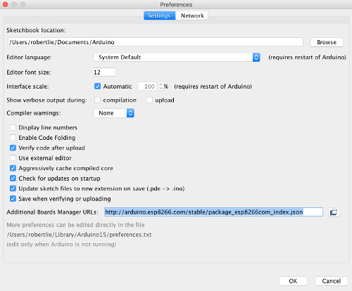
Enter in the Additional Board Manager URLs field: http://arduino.esp8266.com/stable/package_esp8266com_index.json
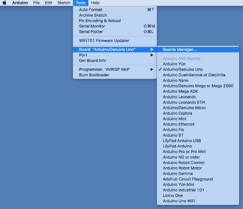
Select menu: Tools > Board > Board Manager...
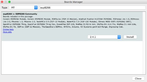
In the search field, type: esp8266
Click the found package.
Select the latest version and press the Install button.
Select menu: Tools
You will see additional menu options.
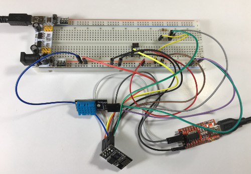
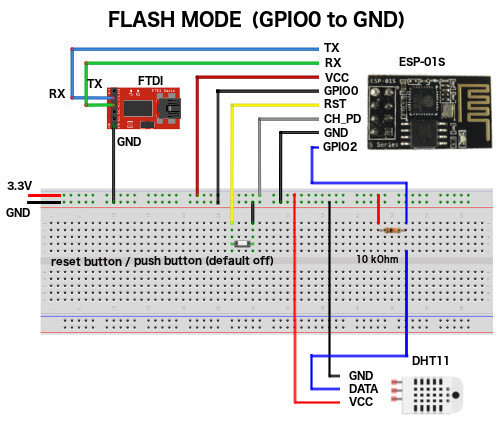
Connect the FTDI adapter to the ESP-01S using the jumper wires.
ESP-01S
FTDI
Breadboard power supply module
RX
TX
VCC
CH_PD (EN)
3.3 V (DO NOT USE THE 5V OUTPUT!!!)
RST (connected to a push button)
GND
GND
GND
TX
RX
GPIO0 (Flash mode)
GND
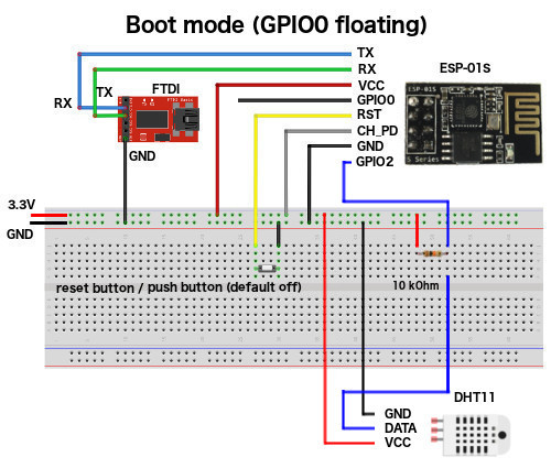
GPIO0 (Boot mode)
Note 1:
The following pins are not used:
ESP-01S GPIO2
FTDI DTR
FTDI CTS
FTDI VCC
Note 2:
The ESP-01S requires too much current which the FTDI VCC output can not deliver.
That is why the breadboard power supply module is needed.
Because of this I will not use the FTDI VCC output, but just in case set the FTDI jumper to 3.3V.
MAKE SURE YOU USE THE BREADBOARD 3.3 V OUTPUT!
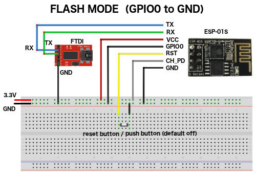
The ESP8266 has two modes:
Flash mode
This mode is also known as "UART download mode".
This mode is used for uploading new firmware or program (eg. Arduino sketch) to the module's flash memory (aka flashing).
To set the ESP8266 chip in this mode:
- Connect GPIO0 to ground.
- Press and release the reset button.
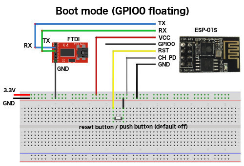
Boot mode
This mode is also known as "Flash boot mode".
This mode is used for normal startup and execution of existing firmware or program.
To set the ESP8266 chip in this mode:
- Connect GPIO0 to nothing (floating).
- Press and release the reset button.
Depending on your FTDI adapter you might need to install a FTDI USB Serial driver.
My FTDI adapter uses the FT232RL chip.
I have installed the FTDIUSBSerialDriver (Virtual COM Port Drivers v2.4.2 for Mac OS X 10.9 and above) which is an implementation of a serial driver for FTDI USB devices on Mac OS X.
It supports FT8U232AM, FT8U245AM, FT232BM, FT245BM, FT2232, FT232R, FT245R, FT2232H, FT4232H, FT232H and FT X Series devices.
This driver (FTDIUSBSerialDriver_v2_4_2.dmg) can be found at: https://ftdichip.com/drivers/vcp-drivers/
But this installed FTDIUSBSerialDriver causes a huge problem!
It only allows me to upload 3 sketches. The 4th sketch hangs during the upload.
To fix this problem, I need to restart my computer. This is not good!
I decided to remove the installed FTDIUSBSerialDriver and use the standard AppleUSBFTDI driver which comes with macOS.
To remove the previous installed FTDIUSBSerialDriver:
Find if the com.FTDI.driver.FTDIUSBSerialDriver is installed.
Type: pkgutil --pkgs | grep -i ftdi
Get list of installed files.
Type: pkgutil --files com.FTDI.driver.FTDIUSBSerialDriver
Delete the files.
Type: sudo rm -r /Library/Extensions/FTDIUSBSerialDriver.kext
Forget the package.
Type: sudo pkgutil --forget com.FTDI.driver.FTDIUSBSerialDriver
If you are using macOS 10.13 (High Sierra) or higher DO NOT install the FTDIUSBSerialDriver.
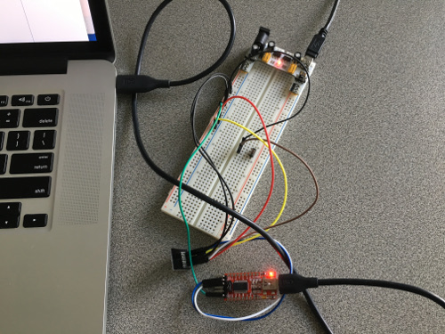
Connect the FTDI adapter to your computer.
Note:
To check which port is used.
Type: ls -al /dev/tty.*
Output: /dev/tty.usbserial-A9M9DV3R
To check which FTDI driver is used.
Type: /usr/sbin/kextstat | grep FTDI
Output: com.apple.driver.AppleUSBFTDI
Now lets do some simple tests. First, lets check if I can set the ESP8266 chip in boot mode.
Use the Boot mode wiring (see wiring schema above, GPIO0 floating)
Select the port, select menu: Tools > Port > /dev/cu.usbserial-A9M9DV3R
Note: Your port name may differ.
Select menu: Tools > Serial Monitor.
Monitor opens, select: Both NL & CR and select 115200 baud.
Press and release the reset (=push) button.
You should see:
Ai-Thinker Technology Co. Ltd.
ready
Note:
If you only see weird characters, lower the baud rate, and press and release the reset button and check if you see the message.
If not repeat these steps.
After you found the correct baud rate, enter the AT command: AT
You should see: OK
Note:
The ESP8266 WiFi module comes pre-programmed with an AT command set firmware.
Enter AT command: AT+GMR
You should see:
AT+GMR
AT version:0.21.0.0
SDK version:0.9.5
OK
Note:
If you have previously uploaded a sketch to the ESP-01S module, the firmware is erased.
You will not see above mentioned AT command outputs.
In this tutorial I will not be using the AT commands, I just inform you about its existence.
Download the dht11-esp01s project on your computer:
Type: git clone https://github.com/robertlie/dht11-esp01s.git
Now lets check if I can set the ESP8266 chip in flash mode by uploading a sketch.
If you upload a sketch, it will erase the current ESP8266 firmware.
The AT commands will not work after you upload the sketch but I will demonstrate how to restore this firmware in case you need it in the future.
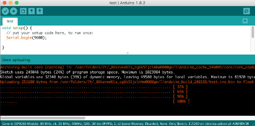
Upload the dht11-esp01s/sketches/test/test.ino sketch to the ESP-01S and run this sketch.
Use the Flash mode wiring (see wiring schema above, GPIO0 to ground)
Select the port, select menu: Tools > Port > /dev/cu.usbserial-A9M9DV3R
Note: Your port name may differ.
Upload the test.ino sketch, select menu: File > Select the test.ino file.
Press the verify button to verify the sketch. Make sure there are no errors.
Press and release the reset (=push) button.
Press the upload button to upload the sketch to the ESP-01S.
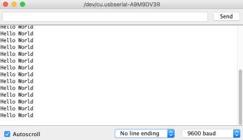
Open the Serial monitor, select menu: Tools > Serial Monitor.
Make sure the baud rate is set to 9600 baud (bottom right)
The text "Hello World" is displayed every 1 second.
Close the serial monitor
When uploading sketches I sometimes encountered the following "error: espcomm_upload_mem failed".
Solution: Just press and release the reset button (a few times) and upload the sketch again.
As mentioned earlier, the ESP8266 firmware was erased after you uploaded a sketch.
If you want to restore this firmware you can follow this procedure.
Reinstalling the firmware is ONLY needed if you want to play with the AT commands.
This tutorial is not about using the AT commands!
If you are not interested in AT commands you can skip this step.
The latest version of Mac OS X, High Sierra, comes with Python 2.7 out of the box.
You do not need to install or configure anything else to use Python.
Open a terminal and check your installed python version, type: python --version
You should see: Python 2.7.10
Install the esptool using the Python Package Manager (pip) which should already be installed on a macOS High Sierra.
Type: sudo pip install esptool
Note:
The esptool is a Python-based, open source, platform independent, utility to communicate with the ROM bootloader in Espressif ESP8266 & ESP32 chips.
The Arduino IDE also uses an esptool to upload the compiled sketch to the ESP-01S module.
This esptool is located at:
~/Library/Arduino15/packages/esp8266/tools/esptool/0.4.13/
To upload the firmware I am using the python esptool and NOT the one used by the Arduino IDE.
I have copied the ai-thinker-0.9.5.2.bin (default baud rate is 115200) firmware in my dht11-esp01s project.
Now lets upload this firmware to the ESP-01S module:
Use the Flash mode wiring (see wiring schema above, GPIO0 to ground)
Power up the breadboard power supply module.
Connect the FTDI adapter to your computer.
Open a terminal.
Type: cd ~
Type: cd dht11-esp01s/esp8266_firmware
Ensure that the ESP8266 chip is fully erased before flashing:
Press and release the reset (=push) button.
Type: esptool.py --port /dev/cu.usbserial-A9M9DV3R erase_flash
Note:
To find your port, type: ls -al /dev/tty.*
Upload firmware:
Press and release the reset (=push) button.
Type: esptool.py --port /dev/cu.usbserial-A9M9DV3R write_flash -fm qio 0x00000 ai-thinker-0.9.5.2.bin
Output:
esptool.py v2.5.0
Serial port /dev/cu.usbserial-A9M9DV3R
Connecting....
Detecting chip type... ESP8266
Chip is ESP8266EX
Features: WiFi
MAC: xx:xx:xx:xx:xx:xx
Uploading stub...
Running stub...
Stub running...
Chip ID: 0x008e2345
Hard resetting via RTS pin...
The firmware is uploaded.
Now you can enter AT commands again.
Connect the DHT11 sensor to ESP-01S using the jumper wires.
Connect a 10kΩ resistor from DHT11 data pin to 3.3V pin breadboard power supply module.
DHT11
ESP-01S
FTDI
Breadboard power supply module
RX
TX
VCC
VCC
CH_PD (EN)
3.3 V (DO NOT USE THE 5V OUTPUT!!!)
GND
RST (connected to a push button)
GND
GND
GND
TX
RX
DATA
GPIO2
DATA - 10kΩ
3.3 V
GPIO0 (Flash mode)
GND
GPIO0 (Boot mode)
Note 1:
The following pins are not used:
FTDI DTR
FTDI CTS
FTDI VCC
The ESP8266 has two modes:
Flash mode
This mode is also known as "UART download mode".
This mode is used for uploading new firmware or program (eg. Arduino sketch) to the module's flash memory (aka flashing).
To set the ESP8266 chip in this mode:
- Connect GPIO0 to ground.
- Press and release the reset button.
Boot mode
This mode is also known as "Flash boot mode".
This mode is used for normal startup and execution of existing firmware or program.
To set the ESP8266 chip in this mode:
- Connect GPIO0 to nothing (floating).
- Press and release the reset button.
Make changes to this sketch according to your situation:
Your WiFI ssid and password.
Upload the sketch to the ESP-01S module.
Set the ESP-01S in boot mode (GPIO0 floating).
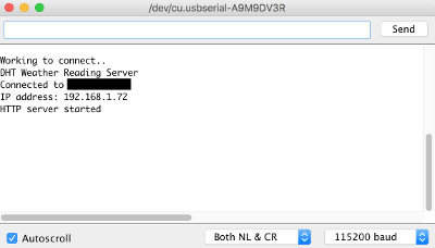
Open the Serial Monitor and set the baud rate to 115200
Press and release the reset (=push) button.
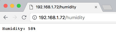
The ip adress is displayed in the Serial Monitor, for example: 192.168.1.72
Open a browser and enter the ip address.
You should see: Hello from the weather esp8266, read from /temp or /humidity
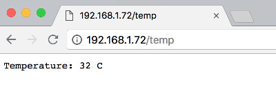
To see your temperature, type: http://192.168.1.72/temp
To see your humidity, type: http://192.168.1.72/humidity
Note:
You need to reload the web page to update the sensor data.
Now lets make the ESP-01S communicate with a mosquitto server. First begin by adding the PubSubClient library to the Arduino IDE. This library is for MQTT messaging and it supports ESP8266.
Start Arduino IDE.
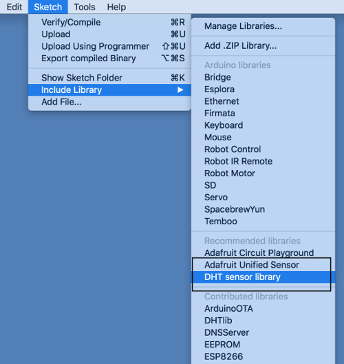
Select menu: Sketch > Include Library > Manage Libraries
Search for: PubSub
Select PubSubClient (Nick O'Leary) and install the latest version (eg: v2.6.0)
Next install Mosquitto (MQTT) on the Raspberry Pi 3.
Mosquitto is an open source message broker that implements the MQTT protocol.
MQTT stands for Message Queuing Telemetry Transport.
Mosquitto is lightweight and is suitable for use on all devices from low power single board computers to full servers.
The MQTT protocol provides a lightweight method of carrying out messaging using a publish/subscribe model.
This makes it suitable for Internet of Things messaging such as with low power sensors or mobile devices such as phones, embedded computers or microcontrollers.
Login to your Raspberry Pi and open a terminal.
Note:
You can use SSH to access your Raspberry Pi.
Type: ssh [email protected]
Type: cd ~
Check what Raspbian version is installed.
Type: cat /etc/os-release
You should see:
PRETTY_NAME="Raspbian GNU/Linux 9 (stretch)"
NAME="Raspbian GNU/Linux"
VERSION_ID="9"
VERSION="9 (stretch)"
ID=raspbian
ID_LIKE=debian
HOME_URL="http://www.raspbian.org/"
SUPPORT_URL="http://www.raspbian.org/RaspbianForums"
BUG_REPORT_URL="http://www.raspbian.org/RaspbianBugs"
Download the signing key.
Type: wget http://repo.mosquitto.org/debian/mosquitto-repo.gpg.key
Add this key to apt-get.
Type: apt-key add mosquitto-repo.gpg.key
Add mosquitto to basic Debian repositories.
To add the repository, first go to the folder containing the repository lists for apt-get.
Type: cd /etc/apt/sources.list.d/
Download the repository list file for Mosquitto.
Type: wget http://repo.mosquitto.org/debian/mosquitto-stretch.list
Note:
I got the error:
E: The repository 'http://archive.raspberrypi.org/debian stretch Release' does no longer have a Release file.
The problem is caused by a bad static DNS IP. To solve this problem:
Type: sudo nano /etc/dhcpcd.conf
Add line: static domain_name_servers=192.168.1.1 //put your DNS ip address
The mosquito server is now up and running. To verify this type: mosquito -v
You should see:
1532504032: mosquitto version 1.5 starting
1532504032: Using default config.
1532504032: Opening ipv4 listen socket on port 1883.
1532504032: Error: Address already in use
To stop the mosquito server, type: sudo /etc/init.d/mosquitto stop
To start the mosquito server, type: sudo /etc/init.d/mosquitto start
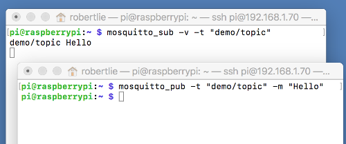
Test mosquitto, open two terminals:
In terminal 1 subscribe to a topic, type: mosquitto_sub -v -t "demo/topic"
In terminal 2 publish a message to a topic, type: mosquitto_pub -t "demo/topic" -m "Hello"
In terminal 1, you should see: demo/topic Hello
Lets restrict access to the broker by setting up a username and password.
Please note the username and password are transmitted in clear text.
If you want better security, you need to implement mosquito SSL.
In this tutorial mosquitto SSL will not be implemenented.
Stop the mosquito server, type: sudo /etc/init.d/mosquitto stop
Type: cd /etc/mosquitto
Create a password.txt file and add a user and corresponding password.
Type: sudo mosquitto_passwd -c password.txt robert
Password: mysecret
Reenter password: mysecret
You can add additional users and passwords to this password.txt file.
Type: sudo mosquitto_passwd -b password.txt bob mybigsecret
To delete a user from this password.txt file.
Type: sudo mosquitto_passwd -D password.txt bob
In this folder you will find the mosquito.conf file.
Make a backup of this file before making changes to it.
Type: cp mosquitto.conf mosquitto.conf_original
Edit the mosquito.conf file.
Type: sudo nano mosquitto.conf
Make changes to this sketch according to your situation:
wifi_ssid, wifi_password, mqtt_server, mqtt_port, mqtt_user and mqtt_password.
Upload the sketch to the ESP-01S module.
Set the ESP-01S in boot mode (GPIO0 floating).
Open the Serial Monitor and set the baud rate to 115200.
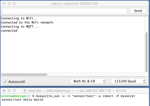
Login to the Raspberry Pi.
Open a terminal and subscribe to a topic (defined in the sketch), type: mosquitto_sub -v -t "sensor/test" -u robert -P mysecret
Each time you press and release the reset (=push) button, the message "Hello World" is published.
This message is displayed in the Raspberry Pi terminal.
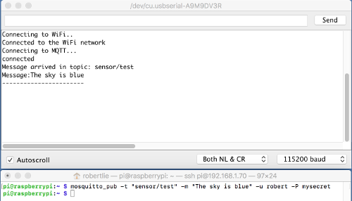
You can also publish a message using the Raspberry Pi terminal and this message is displayed in the Arduino Serial Monitor.
Open another terminal and publish a message, type: mosquitto_pub -t "sensor/test" -m "The sky is blue" -u robert -P mysecret
In the Arduino Serial Monitor you will see this message appear.
Test if the ESP-01S module can publish DHT11 sensor data to the MQTT broker.
Power up the breadboard power supply module.
Connect the FTDI adapter to your computer.
Start Arduino IDE.
Make sure the "Generic 8266 Module" board is selected.
Make changes to this sketch according to your situation:
wifi_ssid, wifi_password, mqtt_server, mqtt_port, mqtt_user and mqtt_password.
Upload the sketch to the ESP-01S module
Set the ESP-01S in boot mode (GPIO0 floating).
Open the Serial Monitor and set the baud rate to 115200
Login to the Raspberry Pi
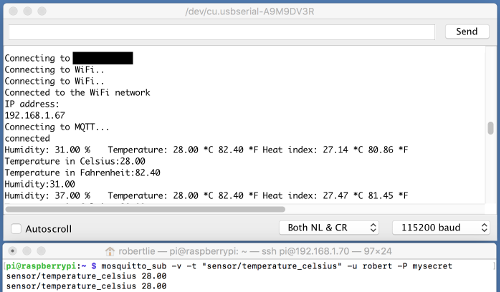
The sketch publishes humidity under topic "sensor/humidity",
temperature in Celsius under topic "sensor/temperature_celsius" and
temperature in Fahrenheit under topic "sensor/temperature_fahrenheit".
For example, open a terminal and subscribe to the temperature celsius topic, type: mosquitto_sub -v -t "sensor/temperature_celsius" -u robert -P mysecret
Press and release the reset (=push) button, the DHT11 sensor data are published and the temperature (celsius)
data is displayed in the Raspberry Pi terminal.
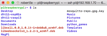
Download and install the dht11-esp01s project on the Raspberry Pi:
Test if the ESP-01S module can publish DHT11 sensor data to the MQTT broker and a nodeJS application subscribes to a topic and displays the sensor data.
Power up the breadboard power supply module.
Connect the FTDI adapter to your computer.
Start Arduino IDE.
Make sure the "Generic 8266 Module" board is selected.
Note:
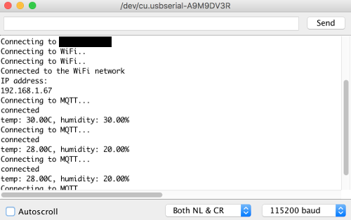
This sketch combines the temperature (Celsius) and humidity to a single message and publish this message to topic "sensor/dht11".
Make changes to this sketch according to your situation:
wifi_ssid, wifi_password, mqtt_server, mqtt_port, mqtt_user and mqtt_password.
Upload the sketch to the ESP-01S module.
Set the ESP-01S in boot mode (GPIO0 floating).
Open the Serial Monitor and set the baud rate to 115200
Press and release the reset (=push) button.
The temperature (Celsius) and humidity are published under topic "sensor/dht11" every 30 seconds (see DHT_mqtt2.ino, MEASUREMENT_TIMEINTERVAL).
Login to the Raspberry Pi
Open a terminal
Type: cd ~
Type: cd dht11-esp01s
Make changes to the dht_mqtt.js according to your situation:
mqtt_user and mqtt_password.
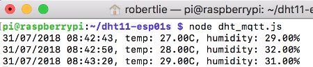
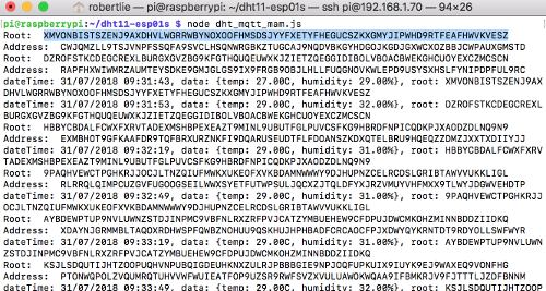
Type: node dht_mqtt.js
The nodeJS application subscribes to topic "sensor/dht11" and displays the sensor data on the screen.
Test if the ESP-01S module can publish DHT11 sensor data to the MQTT broker and a nodeJS application subscribes to a topic. The sensor data is stored on the Tangle Using Masked Authenticated Messaging.
Power up the breadboard power supply module.
Connect the FTDI adapter to your computer.
Start Arduino IDE.
Make sure the "Generic 8266 Module" board is selected.