Sipeed RV Debugger Plus.
Information
https://github.com/sipeed/RV-Debugger-BL702
https://docs.platformio.org/en/latest/plus/debug-tools/sipeed-rv-debugger.html
https://github.com/SeeedDocument/Bazaar_Document/raw/master/openocd.pdf
FT2232D.Schematic.pdf
Operating system used
none
Procedure
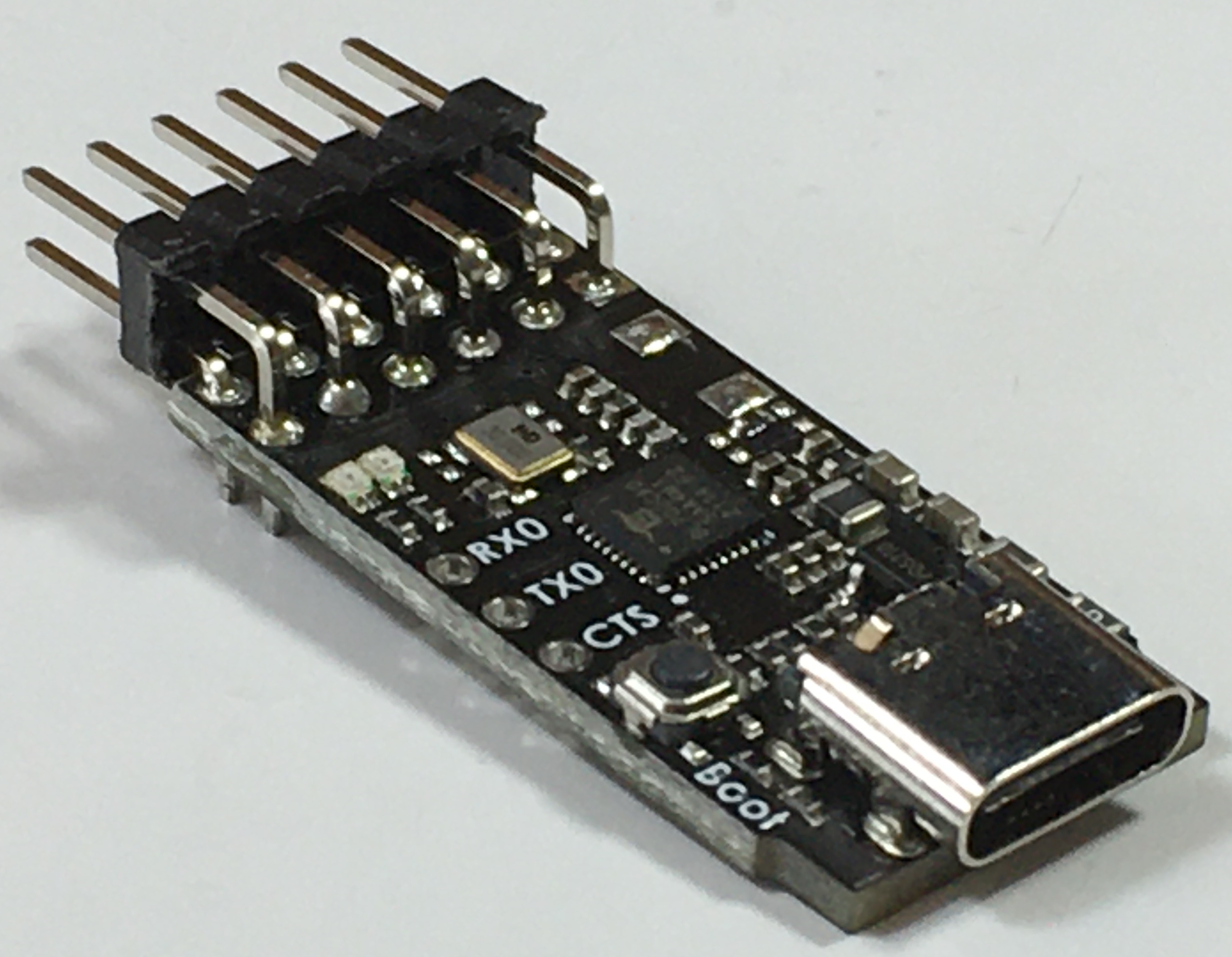
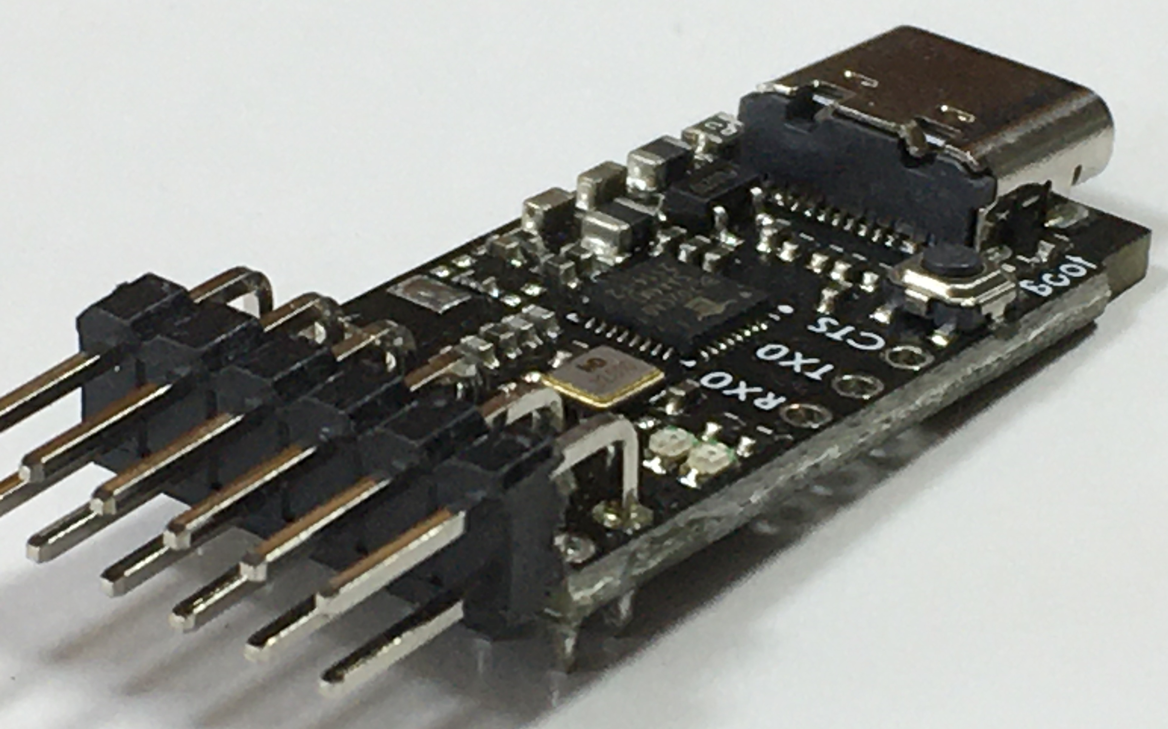
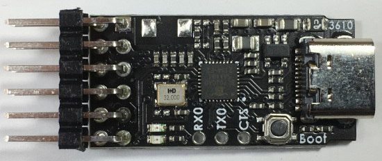
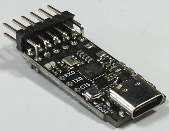
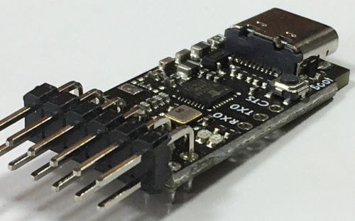
- Sipeed RV Debugger Plus

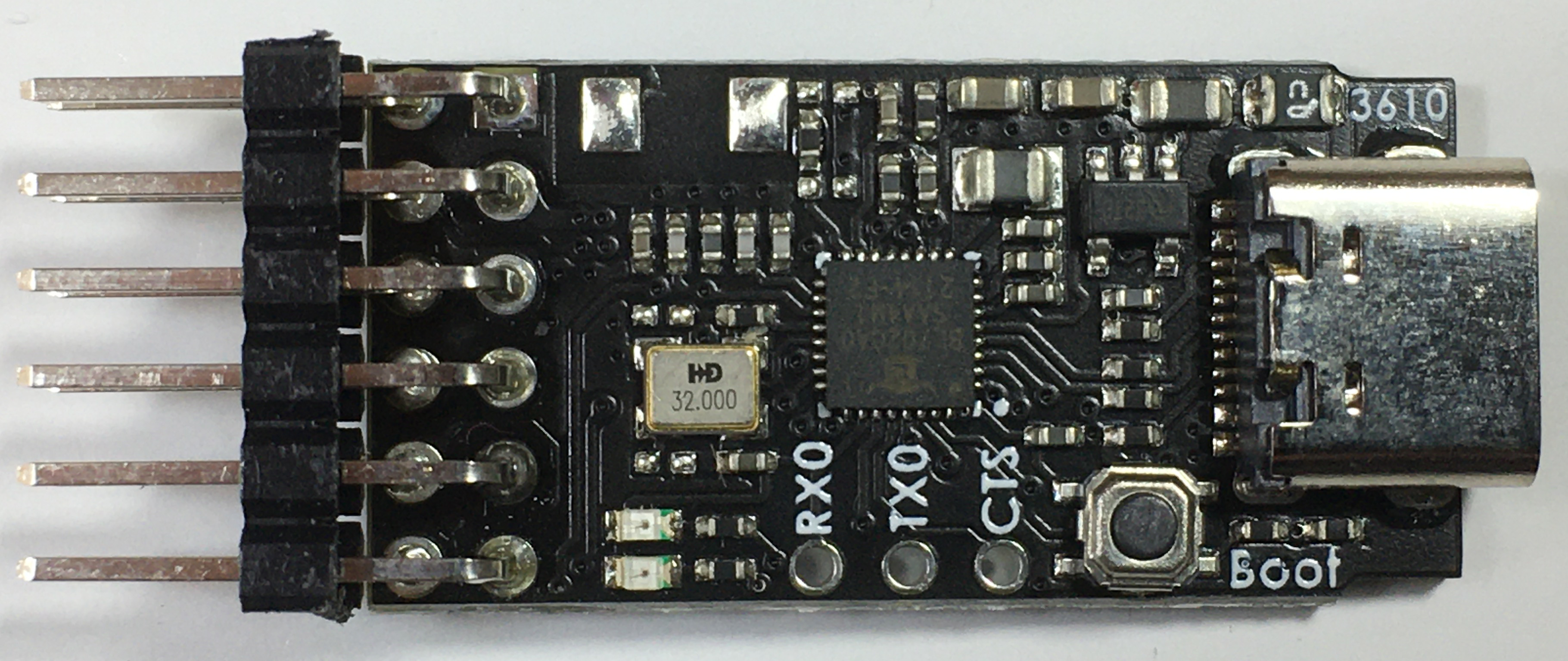
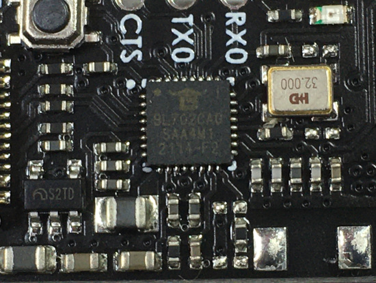
IC markings were difficult to capture:
BL702CA0
SAA4M1
2114-F2
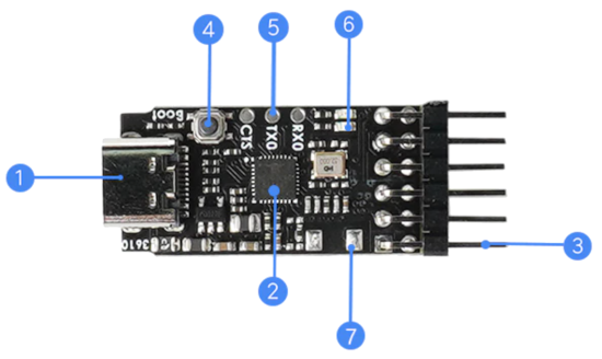
- Sipeed RV Debugger Plus components
|
1
|
USB Type-C
|
|
2
|
Master BL702
|
|
3
|
2.54 mm pitch pin header
|
|
4
|
Boot button
|
|
5
|
Debugging information , debugging serial port
|
|
6
|
Indicator light
|
|
7
|
Reserve 2.4G antenna pad
|
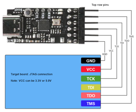
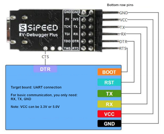
- Interface description
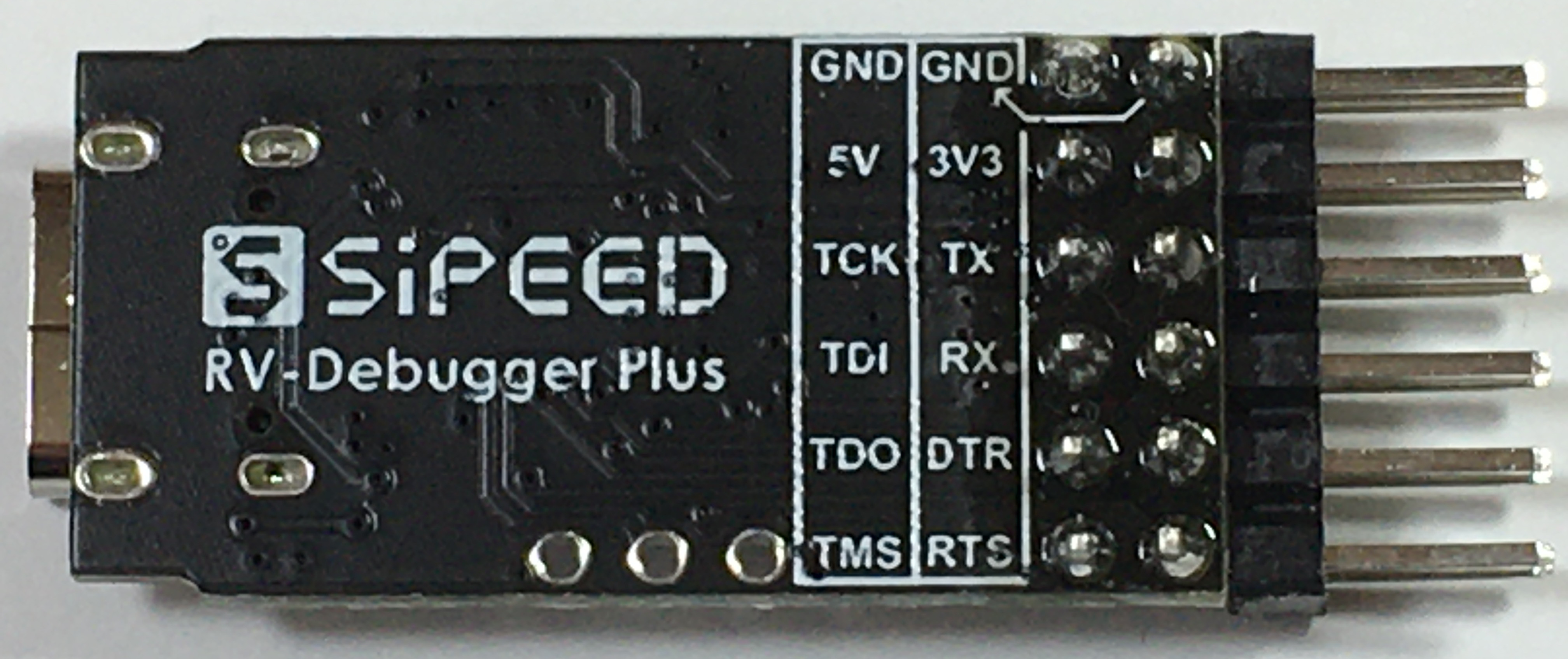
The RV debugger plus has a total of 13 pins of which the tail has 10 pins.
|
3V3
|
3.3V output
|
|
GND
|
Ground
|
|
TX
|
Virtual serial port (UART1) transmitting terminal, the default level is 3.3V
|
|
RX
|
Virtual serial port (UART2) receiving end, the default level is 3.3V
|
|
DTR
|
Virtual serial port (UART1) data terminal ready end, the default level is 3.3V
|
|
RTS
|
Virtual serial port (UART1) request sender, the default level is 3.3V
|
|
5V
|
5.0V output
|
|
GND
|
Ground
|
|
TCK
|
JTAG Test Clock Input, the default level is 3.3V
|
|
TDI
|
JTAG Test Data Input, the default level is 3.3V
|
|
TDO
|
JTAG Test Data Output, the default level is 3.3V
|
|
TMS
|
JTAG Test Mode Selection, the default level is 3.3V
|
|
*RX0
|
Debug information printing serial port (UARTO) sender, the default level is 3.3V
|
|
*TX0
|
Debug information printing serial port (UARTO) sender, the default level is 3.3V
|
|
BOOT
|
BL702 download mode enable terminal, press enable (only need to press when you need to re-burn the firmware).
|
* The default baud rate of UARTO is 2 MHz and techical support for this UART is not provided.
- Hardware connection details.
The RV Debugger Plus is connected to the computer using a USB Type C data cable.
VCC (top pin) is 5V
VCC (bottom pin) is 3V3
|
External power supply voltage requirements
|
4.6 - 5.4 V (Recommend 5.0 V)
|
|
External power supply current demand
|
@ 5V >= 600 mA
|
|
Kit full load current
|
Debugger itself 20 mA
|
|
Range of working temperature
|
0℃ - 75℃
|
|
Temperature rise
|
< 30 K
|
|
BOOT button
|
After pressing and then powering on, the debugger will enter the download mode, please do not use it lightly.
|
|
UART interface
|
The UART1 of the debugger uses push-pull output, so the TX pin may sink current to the target board and cause incomplete power-off.
|
|
Power supply
|
Please do not short-circuit the 5/3V3 and GND pins, otherwise the fuse may be permanently blown.
|
|
Others
|
Please do not hot-plug the periherals of the module with power, otherwise it may cause ElectroStatic Discharge (ESD) damage.
|
- The JTAG of RV Debugger Plus can be used without installing a driver in Windows and Linux.
Theoretically, this also applies to macOS.
The official system has integrated FT2232 driver.
The RV Debugger Plus simulates a standard FT2232HL.
In theory, it is compatible with FT2232 simulation environment.
It is recommended to use the OpenOCD tool chain.
No driver is required to use the virtual serial port.
If unknown hardware appears under Windows, please use a third-party tool to install the driver (such as the driver wizard).
The maximum communication rate of the RV Debugger Plus JTAG is 2.5 Mhz, and the baud rate supported by the virtual serial port is up to 2MJTAG.
Gowin FPGA is not supported temporarily.
Firmware update can be downloaded from:
https://github.com/sipeed/RV-Debugger-BL702
About secondary development:
The main chip BL702 of the RV Debugger Plus integrates the BLE function, so the debugger reserves the corresponding impedance matching circuit and 20x12mm ceramic patch antenna pads when leaving the factory.
If you need secondary development, please refer to the official website link of Boliu Smart for the software SDK. For the hardware part, please go to the Sipeed download site to obtain the corresponding HDK.
Pressing the BOOT button without releasing it and then connecting to the computer will make the RV Debugger Plus enter the download mode.
With the official Bouffalo engineer BLDevCube, it can download the firmware to the debugger.
See the tool usage guide:
http://bouffalolab.gitee.io/bl_mcu_sdk/get_started/bl_dev_cube.html
|