Using Sipeed RV Debugger Plus to upload firmware and to debug code.
Information
none
Operating system used
Windows 10 Pro
Procedure
- With the Sipeed RV Debugger Plus you can upload the firmware to the Sipeed Longan Nano Development and also debug the code.
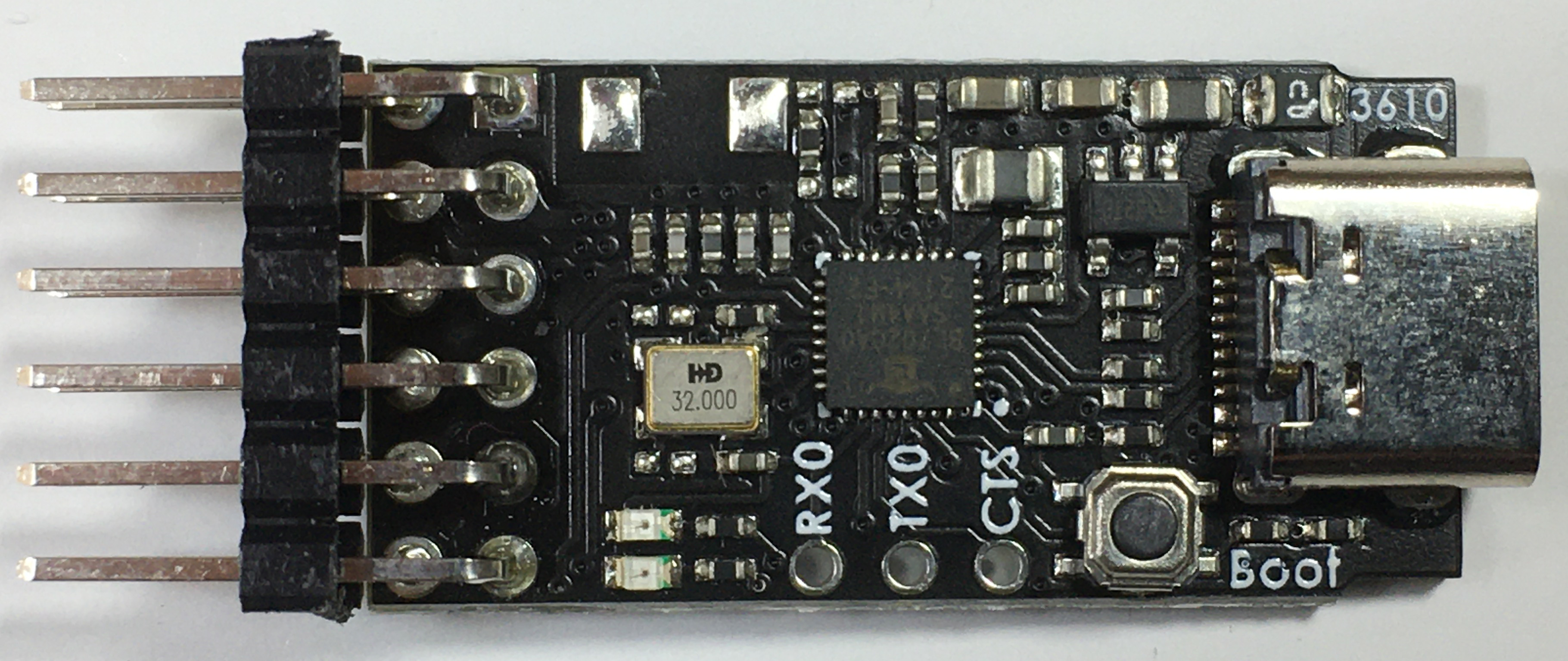
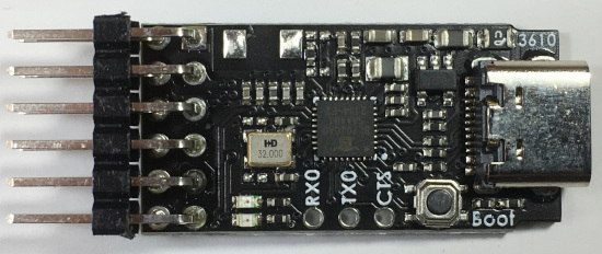
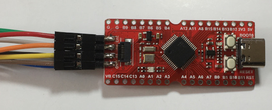
Top view
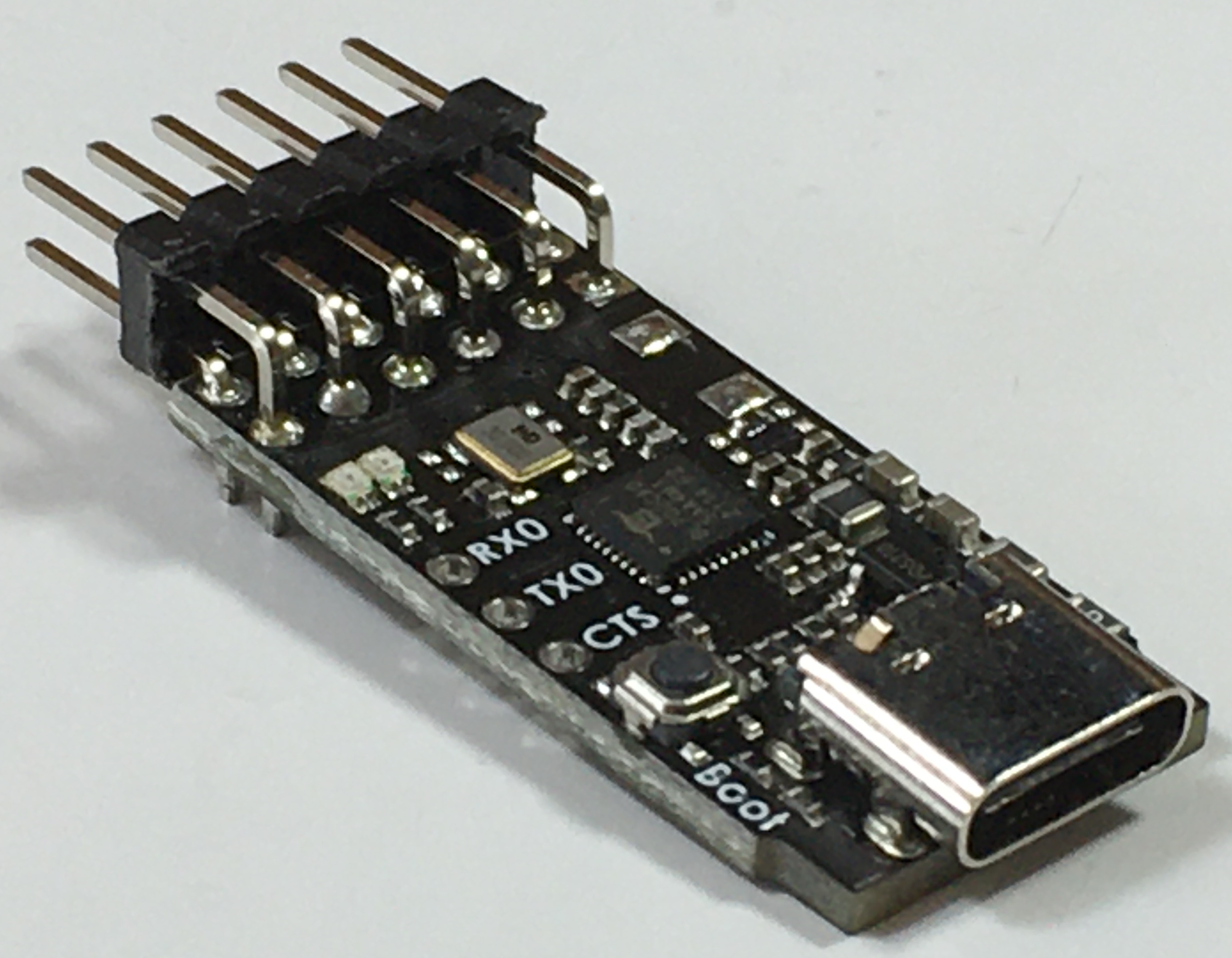
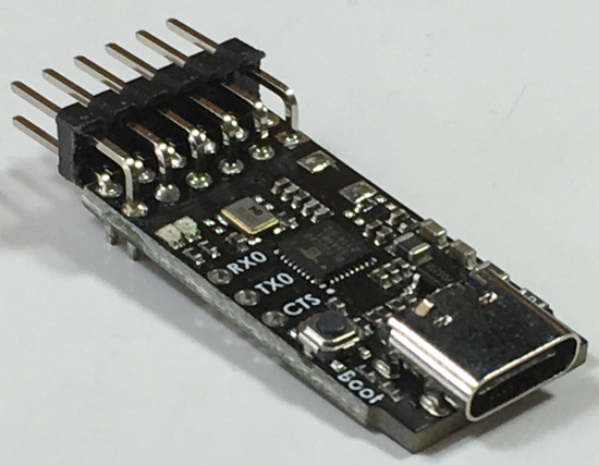
Side view
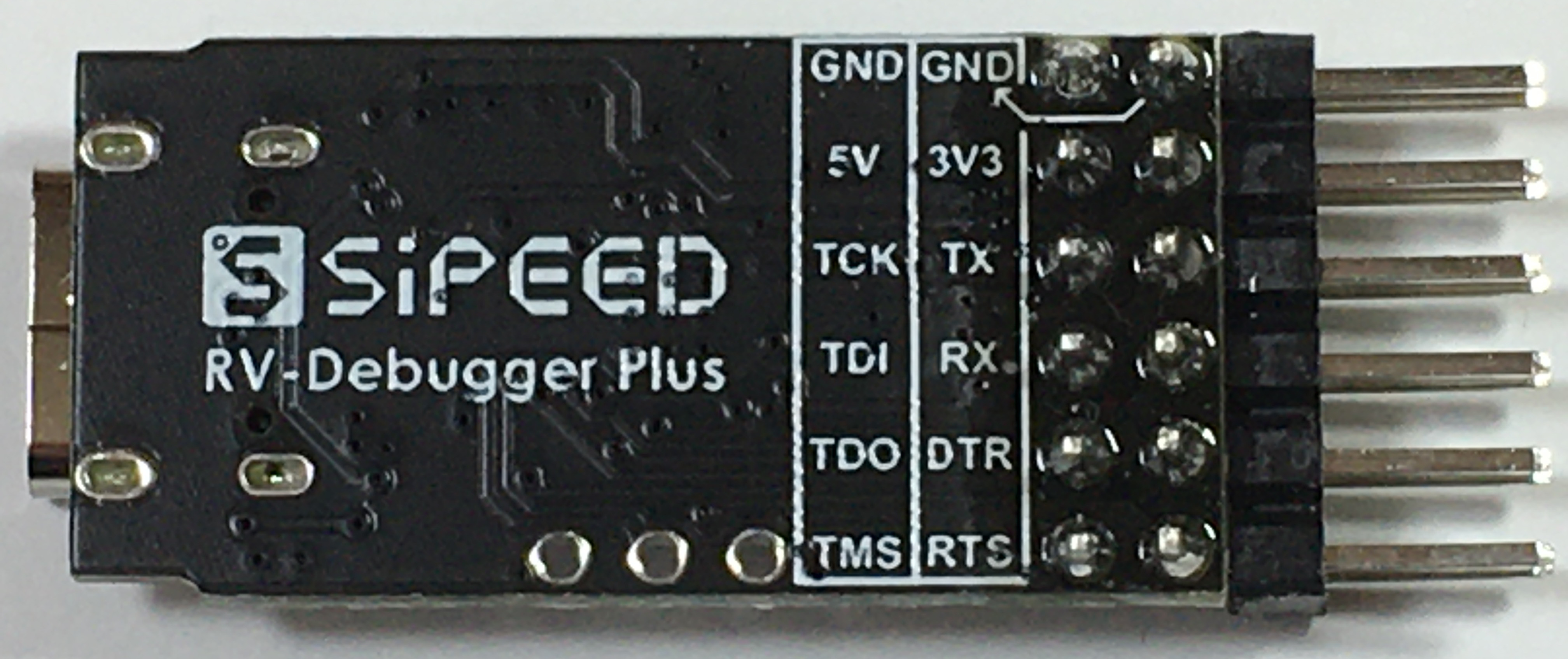
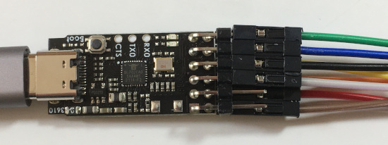
Bottom view

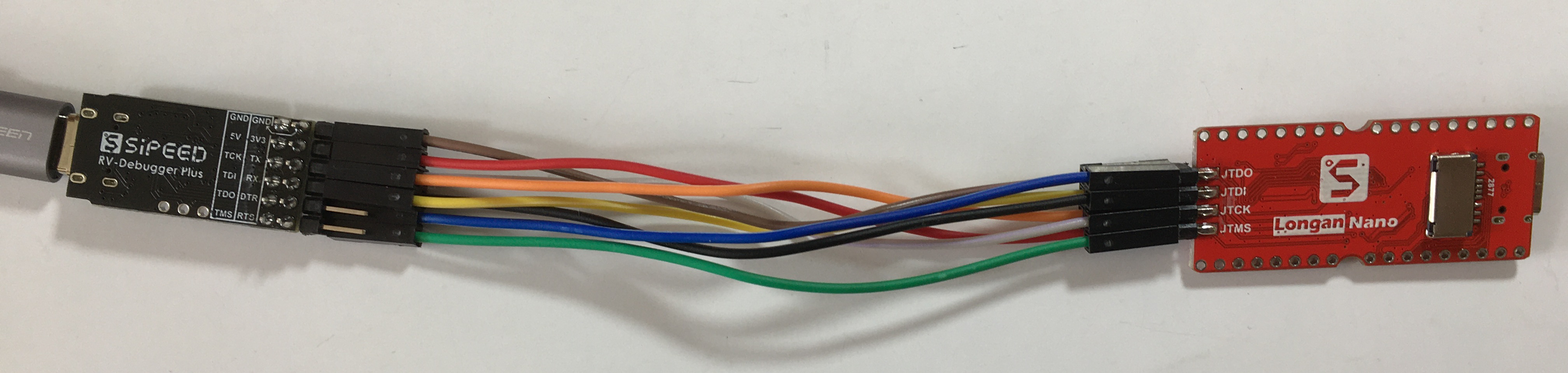
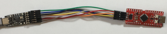
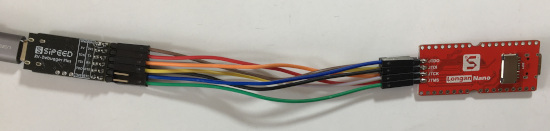
- Connect the Sipeed RV Debugger Plus (on the left) to the Sipeed Longan Nano Development Board (on the right) using 8 female-female jumper wires (12 cm long).
Top view (Click image to enlarge)
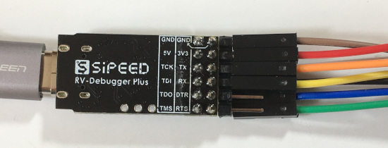
Top view: Sipeed RV Debugger Plus (Pins GND and 5V are not used)
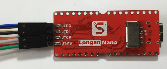
Top view: Sipeed Longan Nano Development Board
Bottom view (Click image to enlarge)
Bottom view: Sipeed RV Debugger Plus (Pins DTR and RTS are not used)
Bottom view: Sipeed Longan Nano Development Board
Connections required to upload firmware to the Sipeed Longan Nano Development Board
| GND |
GND |
| 3V3 |
3V3 |
| TX |
RO |
| RX |
TO |
| DTR (Not connected) |
- |
| RTS (Not connected) |
- |
The Sipeed RV Debugger Plus provides 3V3 to the Sipeed Longan Nano Development Board.
If the provided 3V3 (by Sipeed RV Debugger Plus) is not sufficient when you connect many other hardware components to the development board,
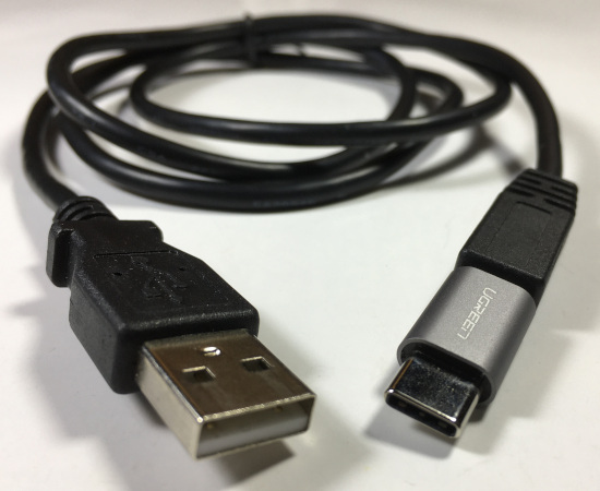
disconnect the 3V3 jumper wire and connect the USB A - USB C cable to the Sipeed Longan Nano Development Board as its power source.
Keep the ground jumper wire connected.
Connections required to debug code
| GND (Not connected) |
- |
| 5V (Not connected) |
- |
| TCK |
JTCK |
| TDI |
JTDI |
| TDO |
JTDO |
| TMS |
JTMS |
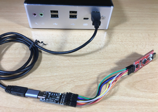
- Connect the Sipeed RV Debugger Plus to the computer using a USB A - USB C cable.
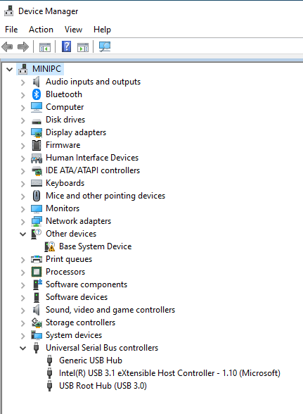
- The Windows Device Manager (devmgmt.msc) automatically detects which COM port is being used when the RV Debugger Plus is plugged in.
If the COM port is not detected, you need to install a Virtual COM port (VCP) driver.
In this example, no COM port was detected when the RV Debugger Plus was plugged in.
Virtual COM port (VCP) drivers cause the USB device to appear as an additional COM port available to the PC. Application software can access the USB device in the same way as it would access a standard COM port.
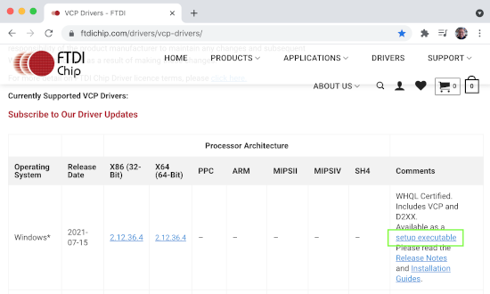
The VCP Drivers, can be found at:
https://ftdichip.com/drivers/vcp-drivers/
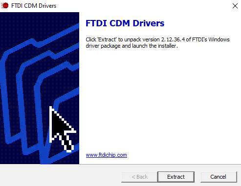
I downloaded the setup_executable file (CDM212364_Setup.zip) and executed CDM212364_Setup.exe to install the Virtual COM port (VCP) driver.
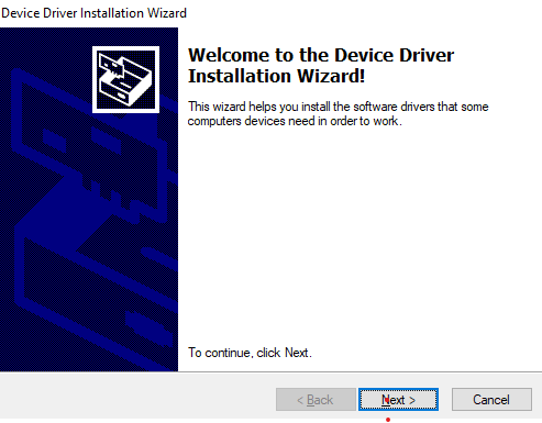
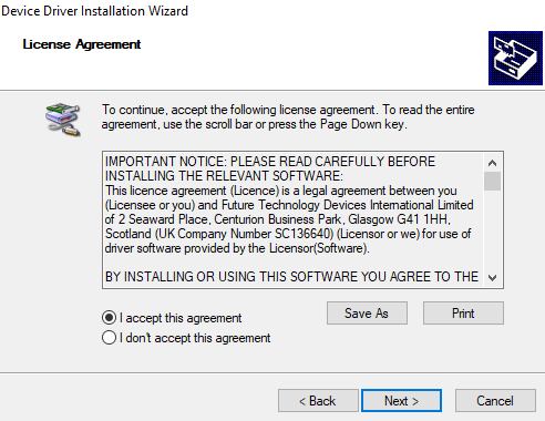
- Install FTDI CDM drivers.
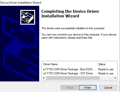
- Now the COM port was detected when the RV Debugger Plus was plugged in.
You will also see USB Serial Converter A and USB Serial Converter B.
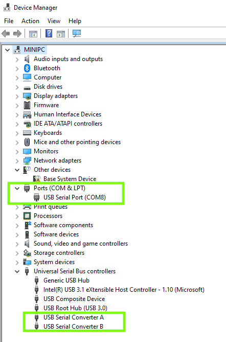
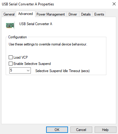
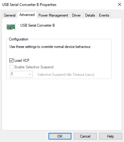
Note:
In case you are curiuos, the reason why you see only one COM port is because USB Serial Converter A, the Load VCP is disabled and
in USB Serial Converter B, the Load VCP is enabled.
But this is not important!
- The Sipeed RV Debugger firmware emulate an FT2232D device.
An FT2232D device has 2 interfaces numbered A and B (or 0 and 1).
Interface A represents JTAG.
Interface B represents UART.
Both interfaces works at the same time independently through the same USB.
Because of the two interfaces your computer will see 2 different devices (actually one composite, in the picture above "USB Composite Device").
The OpenOCD (On-Chip Debugger) is in charge of managing the FT2232D device through USB and at the same time everything related to JTAG.
One interface connects to the JTAG managed by OpenOCD for debugging, and the other interface will look like a virtual COM port for uploading the firmware.
For "USB Serial Converter A" the current FTDI driver must be be replaced by another called WinUSB using the Zadig application.
- Here is the procedure to replace for "USB Serial Converter A" the current FTDI driver with a WinUSB driver.
It is important to follow this procedure in the correct order:
- Goto https://zadig.akeo.ie, download and install Zadig.
Zadig is a Windows application that installs generic USB drivers, such as WinUSB, libusb-win32/libus0_sys or libusbK.
I downloaded Zadig 2.5 (zadig-2.5.exe).
- Start the Zadig executable. Select in the Zadig toolbar: Options | List All Devices
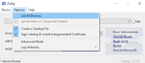
In the bottom left corner you will see how many USB devices it has found.
In this example there are 5 devices found.
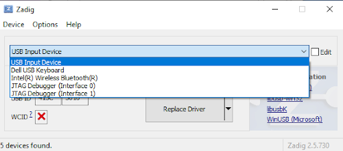
- Select "JTAG Debugger (Interface 0)".
Make sure USB ID = 0403 6010 00 otherwise it is not the correct USB device.
Hardware ID USB\VID_0403&PID_6010&MI_00 is recognized as FTDI (FT2232C/D/H Dual UART/FIFO IC).
Vendor Id = 0403 (Future Technology Devices International, Ltd)
Product Id = 6010 (FT2232C/D/H Dual UART/FIFO IC)
Interface = 00
USB Vendor/Device IDs Database: http://www.linux-usb.org/usb.ids
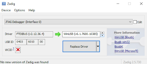
- Make the following changes:
- Select WinUSB (vx.x.xxxx.xxxxx)
- Press Replace Driver button.
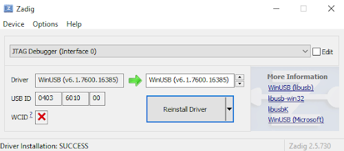
- After the driver is installed, close the Zadig application. This application is not needed anymore.
Lets verify if the WinUSB driver is installed.
Start Windows Device Manager (devmgmt.msc)
You will see it has detected an USB device "JTAG Debugger".
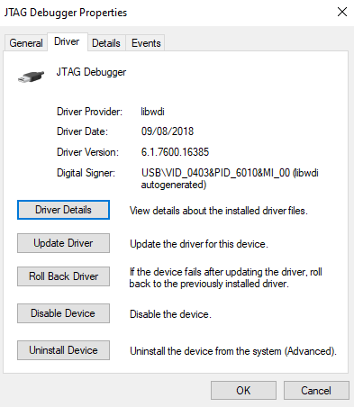
- Double click "JTAG Debugger" and select tab Driver.
You will see Driver Provider: libwdi
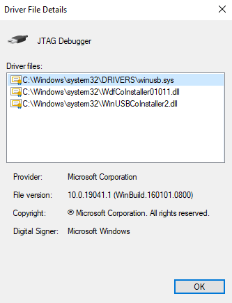
- Press button Driver details. WinUSB is installed.
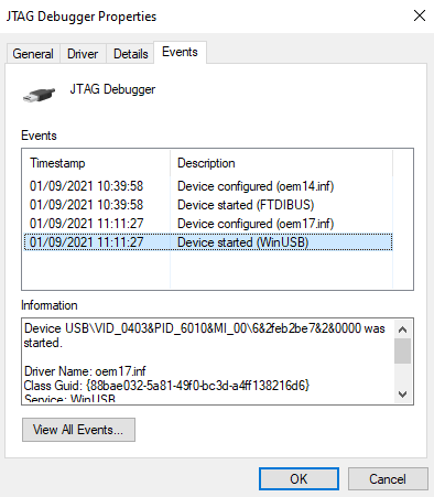
- Select tab Events.
- I have installed the GigaDevice GD32V platform, using the sipeed-longan-nano board and I am using the same Arduino blink project example (Blink.cpp) as demonstrated in tutorial:
Programming the Sipeed Longan Nano using Visual Code and PlatformIO and upload to development board
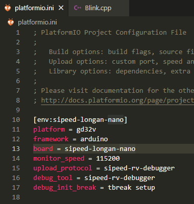
- My platformio.ini file looks like this:
[env:sipeed-longan-nano]
;Platform, choose gd32v
platform = gd32v
;Optional gd32vf103-sdk or arduino
framework = arduino
;Development board
board = sipeed-longan-nano
;Serial monitor baudrate
monitor_speed = 115200
;Default serial, optional jlink, gd-link, dfu, sipeed-rv-debugger
upload_protocol = sipeed-rv-debugger
;jlink, gd-link, ft2232, sipeed-rv-debugger, altera-usb-blaster, um232h, RV-Link
debug_tool = sipeed-rv-debugger
;Set a breakpoint at the start of the setup function
debug_init_break = tbreak setup
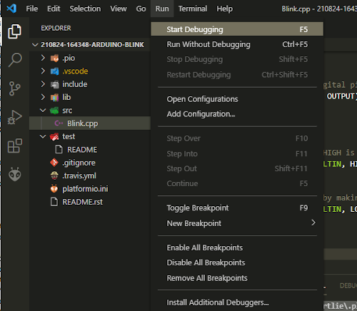
- Start debugging, select in menu: Run | Start Debugging
- Unfortunately I got an error message:
Error: unable to open ftdi device with vid 0403, pid 6010, description 'Dual RS232', serial '*' at bus location '*'
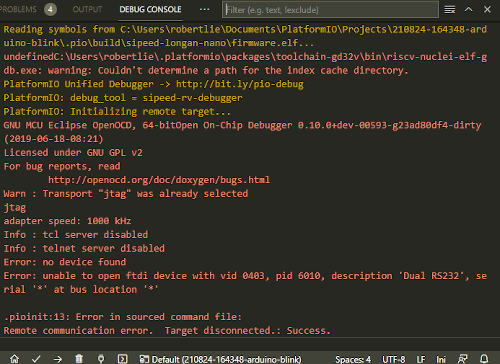
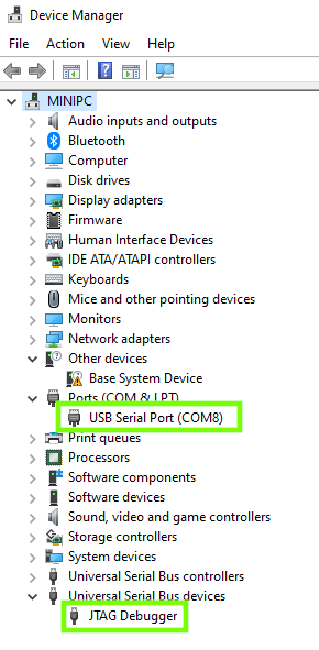
- OpenOCD is looking for an USB device string 'Dual RS232', but the USB device string is 'JTAG Debugger'.
See: Windows Device Manager | Universal Serial Bus Devices | JTAG Debugger
To fix this, goto file:
C:\Users\<user>\.platformio\packages\tool-openocd-gd32v\scripts\interface\ftdi\sipeed-rv-debugger.cfg file.
Change the line:
ftdi_device_desc "Dual RS232"
to
ftdi_device_desc "JTAG Debugger"
This is my modified sipeed-rv-debugger.cfg
- Build and upload the Blink program to the development board.
Terminal output (build): build_rv_debugger_sipeed_longan_arduino_blink.txt
Terminal output (upload): upload_rv_debugger_sipeed_longan_arduino_blink.txt
- The Blink program is now running on the development board.
|